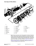


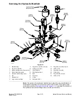

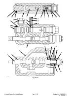


Servicing the Hydraulic Manifold
g345657
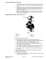
Figure 89
1.
Manifold body
9.
Plug (Zero Leak #4) (10 each)
17.
Plug (Zero Leak #2) (2 each)
2.
Plug (Zero Leak #8)
10.
Spring pin (2 each)
18.
Orifice (.020)
3.
Rotary cartridge valve (flow control) 11.
Plug (SAE #4)
19.
Plug (Zero Leak #6)
4.
Rotary handle assembly
12.
Mow/backlap spool
20.
Check valve
5.
Solenoid relief cartridge valve
13.
Ball
21.
Plug (SAE #6) (2 each)
6.
Nut
14.
Dowel pin
22.
Orifice (.073)
7.
Solenoid coil
15.
O-ring
8.
Logic control cartridge
16.
Ball switch (N.C.)
Note:
The ports on the hydraulic manifold are marked for easy identification of
components. Example: FC is the flow control valve and P1 is the gear pump
connection port (See
Hydraulic Schematic (page 5–11)
to identify the function of
the hydraulic lines and cartridge valves at each port location).
Reelmaster
®
3100-D/3105-D
Page 5–113
Hydraulic System: Service and Repairs
20252SL Rev A
Summary of Contents for 03200 Reelmaster 3100-D
Page 4: ...NOTES NOTES Page 4 Reelmaster 3100 D 3105 D 20252SL Rev A ...
Page 6: ...g341979 Figure 1 Preface Page 6 Reelmaster 3100 D 3105 D 20252SL Rev A ...
Page 10: ...Preface Page 10 Reelmaster 3100 D 3105 D 20252SL Rev A ...
Page 20: ...Safety Safety and Instructional Decals Page 1 10 Reelmaster 3100 D 3105 D 20252SL Rev A ...
Page 44: ...Specifications and Maintenance Special Tools Page 2 24 Reelmaster 3100 D 3105 D 20252SL Rev A ...
Page 224: ...Hydraulic System Service and Repairs Page 5 148 Reelmaster 3100 D 3105 D 20252SL Rev A ...
Page 385: ......