
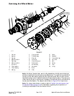


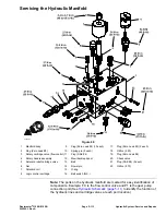
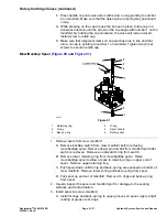

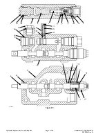


Hydraulic Manifold Assembly
g345584
Figure 88
1.
Flange nut (2 each)
10.
90º hydraulic fitting
19.
O-ring
2.
Stud (2 each)
11.
O-ring
20.
45º hydraulic fitting
3.
90º hydraulic fitting
12.
O-ring
21.
90º hydraulic fitting
4.
Elbow fitting
13.
Hydraulic fitting
22.
O-ring
5.
Hose clamp
14.
O-ring
23.
Tee hydraulic fitting
6.
O-ring
15.
Hydraulic manifold assembly
24.
O-ring
7.
Hydraulic hose
16.
O-ring
25.
Test nipple
8.
O-ring
17.
Hydraulic fitting
26.
Dust cap
9.
Hydraulic fitting
18.
O-ring
Removing the Hydraulic Manifold Assembly
Note:
The ports on the manifold are marked for easy identification of
components. Example: P1 is the gear pump connection port (See
to identify the function of the hydraulic lines and cartridge
valves at each port location).
Reelmaster
®
3100-D/3105-D
Page 5–111
Hydraulic System: Service and Repairs
20252SL Rev A
Summary of Contents for 03200 Reelmaster 3100-D
Page 4: ...NOTES NOTES Page 4 Reelmaster 3100 D 3105 D 20252SL Rev A ...
Page 6: ...g341979 Figure 1 Preface Page 6 Reelmaster 3100 D 3105 D 20252SL Rev A ...
Page 10: ...Preface Page 10 Reelmaster 3100 D 3105 D 20252SL Rev A ...
Page 20: ...Safety Safety and Instructional Decals Page 1 10 Reelmaster 3100 D 3105 D 20252SL Rev A ...
Page 44: ...Specifications and Maintenance Special Tools Page 2 24 Reelmaster 3100 D 3105 D 20252SL Rev A ...
Page 224: ...Hydraulic System Service and Repairs Page 5 148 Reelmaster 3100 D 3105 D 20252SL Rev A ...
Page 385: ......