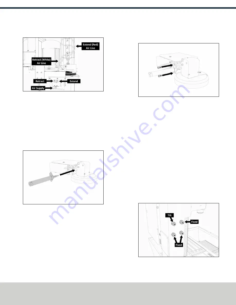
3. Disconnect the air lines from the Retract and Extend ports on
the Power Drawbar.
Figure 2-1: Power Drawbar air line routing.
4. Disconnect the air line from the Air Supply port on the Power
Drawbar button.
5. Remove two M4 × 0.7 - 50 mm socket head cap screws that
secure the Power Drawbar button to the spindle head. Then,
cut the cable ties that secure the air lines together.
6. Remove the Power Drawbar button from the spindle head.
Install the Air Cylinder
1. Attach the air cylinder on to the ATC main assembly.
Figure 2-2: Putting the air cylinder into the ATC main
assembly.
2. Secure the air cylinder to the ATC main assembly with a 12
mm hex wrench (provided) and two M14 × 20 mm socket
head cap screws.
Figure 2-3: Putting the air cylinder hardware into the air
cylinder.
3. Connect the air lines from the ATC main assembly to the air
cylinder as follows:
l
Connect the short air line to the front of the cylinder.
l
Connect the long air line to the back of the cylinder.
Mount the Automatic Tool Changer (ATC) Bracket
1. Identify the four provided standoffs that are used to mount
the ATC to the Z-column:
l
Three fixed standoffs
l
One tilt standoff
2. Remove the flange nuts and the washers from the standoffs,
and then set them aside.
3. Identify and remove the four set screws on the Z-column with
a flat-blade screwdriver.
4. Install the four standoffs on the Z-column as shown in the
following image.
Figure 2-4: Four standoffs installed on the Z-column.
5. Securely tighten the standoffs on the Z-column with a 1-1/2
in. adjustable wrench.
Page 4
©Tormach® 2019
Specifications subject to change without notice.
tormach.com
TD10627: Owner's Guide: 770MX Automatic Tool Changer (ATC) (1019A)
TECHNICAL DOCUMENT


