background image

泰智科技


Shenzhen Topwisdom Technology Co., Ltd


60 

4.4.2 Carving Gradient Sketch Map 


Fig. 4-27 

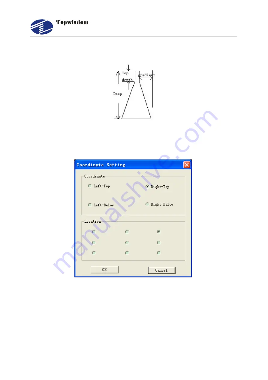
4.4.3 Coordinate System 


Fig. 4-28 

Coordinate:  Coordinate  must  match  original  position  of  the  machine.  On  the  same 
machine can't literally change the coordinate system 

Location:    The position of laser head is the start position before cutting. As shown in 
figure below, there are 9 locations of laser head relative to the position of graphic. The 
red cross is the position of laser head. 

Summary of Contents for TL-403

Page 1: ...Engraving and Cutting Control System Shenzhen Topwisdom Technology Co Ltd Add 4F NO 58 East Side of Yousong Road New Longhua District ShenZhen China 518109 Tel 86 0755 82057902 Fax 86 0755 82057892 We...

Page 2: ...lative parts directly or indirectly Disclaimer Topwisdom Technology reserves the right to modify the content described in this manual without advance notice Topwisdom Technology is not responsible to...

Page 3: ...3 Part 2 Wiring Installation Instruction 5 2 1 System Wiring Diagram 5 2 2 Installation Dimension 6 2 2 1 Panel 6 2 2 2 Mainboard 7 2 3 Wiring Instruction 9 2 3 1 Interface Broad 9 2 3 2 Wiring Diagr...

Page 4: ...ng 33 Part 4 Software Operation Guide 37 4 1 CorelDRAW Direct Output Software Operation 37 4 1 1 Layer Parameter Setting 38 4 1 2 Coordinate Setting 42 4 1 3 Track Setting 43 4 1 4 Single Axis Operati...

Page 5: ...Interface 69 5 2 3 Speed Setting Interface 71 5 2 4 Power Light Intensity Interface 71 5 2 5 Range Preview Interface 72 5 2 6 Single Axis Movement Interface 73 5 2 7 File Selection Interface 73 5 2 8...

Page 6: ...Shenzhen Topwisdom Technology Co Ltd IV 6 3 The PC Connection Question 92 6 4 The Reading and Writing of U disk Question 93...

Page 7: ...ntities of engraving and cutting production Support 5 axises motion control X Y Z U V XY is for laser cutting control Z is feeding axis U is lift axis V is for the second laser cutting head Support do...

Page 8: ...ny motion parts or opening the control equipments when the machine is working or it maybe bring about the accident and machine can t work Prohibit using the electrical equipment in the damp dust corro...

Page 9: ...re cable is larger than 1 0 mm2 1 5 Accessory List The Laser Engraving Control System TL 403 contained the accessories as below Name Qty Introduction Photo Operation Panel 1 For user operation Control...

Page 10: ...Shenzhen Topwisdom Technology Co Ltd 4 PC 3 USB communication extended cable Crossover Ethernet Cable 2 1 Crossover Ethernet Cable 2 Network communication extended cable...

Page 11: ...IR PUL EX5V TL 403C HANDSET NETWORK Air Control Pen Control 5V Relay 5V Relay EX5V DIR PWM DIR PWM DIR PWM DIR PWM DIR PWM DIR PWM DIR PWM DIR PWM Axis V Driver Laser head2 motor Axis Z Driver Feeding...

Page 12: ...Shenzhen Topwisdom Technology Co Ltd 6 2 2 Installation Dimension 2 2 1 Panel The installation dimension of operation panel the unit is MM Face Fig 2 2 Bottom...

Page 13: ...Shenzhen Topwisdom Technology Co Ltd 7 Fig 2 3 2 2 2 Mainboard The installation dimension of mainboard the unit is MM Fig 2 4...

Page 14: ...Shenzhen Topwisdom Technology Co Ltd 8 Fig 2 5...

Page 15: ...5V PWM3 DIR3 XGND IN 1 LASER 2 LASER 1 EX5V XGND IN10 IN 7 IN 8 IN 9 EX5V XGND IN11 IN12 IN13 EXV EXV OUT7 OUT8 EX5V XGND PWM6 DIR6 EX5V XGND PWM5 DIR5 EX5V XGND PWM2 DIR2 EX5V XGND PWM1 DIR1 X DRIVER...

Page 16: ...DIR ENA ENA GND DIR1 PWM1 5V GND U V W Vdc 36V To Motor 36V J20 X Driver Fig 2 7 2 Panasonic Servo Wiring PULS1 PULS2 SIGN1 SIGN2 GND DIR1 PWM1 5V COM U V W COM 24V To Motor 24V J20 Panasonic servo 3...

Page 17: ...CO2 Laser Power Supply Wiring TTL H TTL L WP GND DAC 1 3 4 5 6 2 Water Potect EX5V PWM3 DIR3 IN 1 XGND J2 Laser Power Supply Active low Fig 2 9 2 RF Laser Wiring Power Water Protect EX5V PWM3 DIR3 IN...

Page 18: ...t of the laser Generally PWM Frequency is 5000Hz And set the Laser Max parameter not larger than 95 especially not to set as 100 otherwise it works improperly 2 3 2 3 Blowing Air Signal Wiring EXV OUT...

Page 19: ...2 4 1 Power Signal The system is dual 5V power supply The system internal 5V power interface J24 switching power interface Pin Definition 1 5V Internal 5V power source positive input 2 GND Internal 5V...

Page 20: ...twork 2 4 5 Output The driver interface X axis interface J20 Pin Definition 1 EX5V External 5V power source positive output PUL DIR 2 PWM1 Step pulse output PUL 3 DIR1 Direction signal output DIR 4 GN...

Page 21: ...rounding output U axis interface J11 Pin Definition 1 EX5V External 5V power source positive output PUL DIR 2 OUT3 Step pulse output PUL 3 OUT4 Direction signal output DIR The general output interface...

Page 22: ...erface of laser power 1 J2 Pin Definition 1 EX5V External 5V power source positive output 2 PWM3 Be used to control the laser When the laser is RF laser used to control the power intensity and light o...

Page 23: ...jumper to H the signal is high and effective to L the signal is low and effective When the laser is domestic glass tube used to control laser On Off 4 IN 6 Laser status the corresponding instruction i...

Page 24: ...limit axis movement to the minimum coordinate 0 limit sensor input 4 IN 9 Opening protection signal input 5 IN 10 Foot switch signal input 6 XGND External 5V power source grounding output The general...

Page 25: ...the corresponding parameters of upper PC must be set as Positive by PNP When using straight or magnetic induction switch the corresponding parameters of upper PC must be set as Negative while receivi...

Page 26: ...lled firstly Then double click the icon below CorelCamera_V8 7 8 is used to introduce a screen shown in Fig 3 1 will be displayed for selecting installing language Fig 3 1 Click next to proceed with i...

Page 27: ...install path as shown in Fig 3 4 select the Corel Graphics 12 folder as below Fig 3 4 When the installed path is found click the Confirm to go back to the screen shown in Fig 3 3 Then click the Manual...

Page 28: ...inished the screen shown in Fig 3 5 is displayed Click OK to finish However the installation is not really completed then as you need to make configurations for the CorelDRAW software after the config...

Page 29: ...software The CarveNorNor folder in the root folder of CoreDRAW application and the CORELSAVE_NOR folder in Draw folder can be manually deleted if it was needed 3 3 Installing CAD Direct Output Now the...

Page 30: ...then the screen shown in Fig 3 8 is displayed Fig 3 8 Click Next to proceed with installation Fig 3 9 When finished selecting language click button to select the install path Then click Next to start...

Page 31: ...Ltd 25 Fig 3 10 When the installation is finish the installing program will be closed automatically 3 4 Uninstalling CAD Direct Output Click the LaserT Uninstall show as Fig 3 11 Fig 3 11 Click Yes t...

Page 32: ...echnology Co Ltd 26 Fig 3 13 3 5 USB Driver Installation Insert the USB Cable the power on Fig 3 14 will be shown on the Compute and then the Fig 3 15 will be shown Fig 3 14 Fig 3 15 Select No not thi...

Page 33: ...Co Ltd 27 Click the Next show as Fig 3 16 Fig 3 16 Click the Next show as Fig 3 17 Fig 3 17 Select Install from a list or specific location Advance Click the Next Click Include this location in the s...

Page 34: ...licking the browse button Once the file path has been entered in the box click next to proceed Fig 3 18 The screen shown in Fig 3 19 will be displayed as Windows XP copies the required driver files Fi...

Page 35: ...After the engraving card power on connect the PC with USB cable the computer will assign a COM port to communicate But when the assigned COM port is more than COM8 the communication will have problem...

Page 36: ...Shenzhen Topwisdom Technology Co Ltd 30 Fig 3 21 Double click the System show as Fig 3 22 Fig 3 22...

Page 37: ...Shenzhen Topwisdom Technology Co Ltd 31 Fig 3 23 Click the device management Fig 3 24 The assigned COM port...

Page 38: ...M4 is the assigned COM port the way and the steps that change the assigned COM port are as follow Double click USB Serial Port COM4 show a window single click Port settings show as Fig 3 25 Fig 3 25 C...

Page 39: ...Shenzhen Topwisdom Technology Co Ltd 33 Fig 3 26 Click OK display a window of Communications Port Properties as Fig 3 27 Fig 3 27 Click Yes to finish 3 7 IP Setting Enter the control panel...

Page 40: ...Shenzhen Topwisdom Technology Co Ltd 34 Fig 3 28 Double click network connection Fig 3 29 Double click Local Connection...

Page 41: ...Shenzhen Topwisdom Technology Co Ltd 35 Fig 3 30 Double click TCP IP setting Fig 3 31...

Page 42: ...Shenzhen Topwisdom Technology Co Ltd 36 Select Use the following IP address set the IP Subnet mask Default gateway as below figure Fig 3 32...

Page 43: ...n Open the CorelDRAW software show as Fig 4 1 Fig 4 1After startup our processing buttons will be automatically mounted on the menu shown in Fig 4 1 as pointed out by the arrow After completing the fi...

Page 44: ...onfiguration of engraving parameters if there are imported bitmaps there will be independent bitmap settings You can select a certain color and double click or click on button Parameter Settings for s...

Page 45: ...the settings for Carve follow the same way When the check box of default is selected no need to set the power intensity and speed and the default values of the machine will be adopted settings for po...

Page 46: ...various thickness By adjusting the position of laser head to make the laser head move to the position of the laser focal length is reach Hit_point for hit point or drill on material Firstly click the...

Page 47: ...h determines the distance from the top to the bottom the greater the distance the slope more flat Fig 4 5 Precision the precision of engraving The unit is DPI or DMP It means how many lines will be pr...

Page 48: ...set the backlash in different speed Because of working in different speed the backlash is different The greater speed the bigger the backlash After the parameter settings the engraving output can be...

Page 49: ...etting Click the TrackSet button in Fig 4 2 a track setting window will be shown It can set the cutting order and the cutting start point of the line in different shape or layer As shown in Fig 4 9 Fi...

Page 50: ...utton At this time the upper left window will display the new processing order of shapes the Show Order check box is selected Enter Line When Selected the enter Line check box an extension line will b...

Page 51: ...ance in MoveSize edit box and the move speed in Speed edit box If you need the laser on set the laser power in Power edit box and select the OpenLaser check box Click Execute button to move If you wan...

Page 52: ...ding The Unit is second Attention These parameters above are applied to array process or repeat process Here the row and the column is array parameters If row is 2 and column is 1 then 2X1 array work...

Page 53: ...tance from ending position of current shape to starting position of next shape is shortest The free move time is shortest Smooth starting point Select the optimal starting position of next shape to re...

Page 54: ...The unit is the greater the value you set the greater the compensation Split feed If the graph is so long it needs to split feed Set the split length And the graph within the split length range will n...

Page 55: ...he downloaded file at the last Select it and press start to process Exit Close the output window Fig 4 14 4 2 The Equipment Management This section describes the parameter settings of the laser engrav...

Page 56: ...u Fig 4 16 4 17 This software functions to make settings for the equipment parameters of Topwisdom laser engraving software 4 2 1 Toolbar There are 3 buttons in the tool bar respectively representing...

Page 57: ...ead Read the parameters saved in the equipment and display the values to the user for reference If you need to modify the parameters you must read the parameters in the equipment or open the parameter...

Page 58: ...y the professionals generally don t recommend customers to use Laser Type Select proper laser device type according to the laser device used by the machine PWM Frequency I e the power intensity freque...

Page 59: ...espond to directions of the motion of the axes if it moves to the right when you press the left change the polarity Note set the limit polarity first then direction polarity and key polarity last Move...

Page 60: ...it box and 30 into the WiseSize edit box Click ok the program will calculate out the right resolution Other Axis is similar When calculate the resolution of Y the RealSize is the length of trace the b...

Page 61: ...d carved to obtain the very good effect In general the user can set the parameters reasonable according to their requirement for engraving speed and accuracy To meet the accuracy requirement of the us...

Page 62: ...ap for engraving click on the import bitmap button in Fig 4 20 a Import set window will be shown If you need to change the bitmap into reseau diagram select the NetMode check box You can set the direc...

Page 63: ...ision Set the curve accuracy with the software to improve the smoothness and speed of the operation you can select general meddle high very high most high etc Fig 4 22 4 3 CAD Direct Output Software O...

Page 64: ...lect corresponding options in the window shown in Fig 4 24 First you d like to announce that we do not support text and annotations to a fractional however there are some limitations for example we su...

Page 65: ...ng tool is selected the menu shown in Figure Fig 4 26 will appear when inputting text Fig 4 26 Then you just let it adopt the default font shown in Figure Fig 4 26 Do not select the English fonts or S...

Page 66: ...rdinate must match original position of the machine On the same machine can t literally change the coordinate system Location The position of laser head is the start position before cutting As shown i...

Page 67: ...hows the effects of the origin drawing and the drawing after Carving output as there s no difference of intaglio and incised inscription in vector graphics you may get the effect of incised inscriptio...

Page 68: ...erent colors are in the relation of inclusion no influence on each other There s overlay between the two parts of Carvings We believe you may have deeper understanding for the Carving modes of AutoCAD...

Page 69: ...to the end b one run There are 2 ways to solve this problem 1 draw the drawings in order or combine them with the merger operation provided in software like CorelDRAW or AutoCAD etc 2 our software en...

Page 70: ...like human being for instance cutting the external rectangle before the internal part etc Therefore we must pay attention to this kind of drawing when drawing e g if you want to cut the two rectangles...

Page 71: ...e so large and cannot be seen when opened in another software after zooming out and the breadth of output will be far exceeding the operation breadth of the equipment which will also cause problems Pa...

Page 72: ...5 1 The Panel Operation and Buttons Function Introduction 5 1 1 The Panel Fig 5 1 5 1 2 Buttons Function Introduction 1 Emergency Stop key no matter what state the machine click the key it ll be into...

Page 73: ...se to test touch a time light a time used to test the optical path 9 Origin Key Can set the start point from which the machine runs The Origin can be freely chosen on the Machine setting parameters If...

Page 74: ...int 15 Number Keys change the data the selected area also can directly press the key to choose the current menu 16 Decimal Key 17 Delete key 18 Z axis moving key in the Processing and Event into inter...

Page 75: ...d Valid KeySpeed Middle PX 200 1V 2X Idle 00 00 00 30 PY 0 000 0 000 12345678 OUT Network Disconnect 2014 03 10 10 58 Complete Power1 1 5 30 Power2 5 Fig 5 3 The top of the interface shows the file na...

Page 76: ...Select key to change the speed there are Fast Middle Slow PX PY The coordinate in the current place When there is no file Selected It displays the default power and speed When selecting the file it s...

Page 77: ...rent layer Otherwise it shows the system default speed value The unit is mm s Idle Speed The default move speed when laser is off When one file is selected it shows the idle speed in current layer Oth...

Page 78: ...x When stroking curves this power intensity is applied as the work speed was reached Or it applied for the bottom depth when gradient carving The range is 0 00 100 00 Power Min1 is the min light power...

Page 79: ...le Axis Movement Interface After initialization press Axis key show as M i d d l e N O 0 0 0 0 0 Run 2 If Laser On 1 KeySpeed 3 X Axis Setting 4 Y Axis Setting 5 Z Axis Setting 6 U Axis Setting 7 V Ax...

Page 80: ...Down Up to choose the file press Select key to find the current file press ESC to quit press Enter to operate show as ESC OK 4 Delete Memory File 3 Write to Udisk 1 Read File 5 Delete All 2 File Edit...

Page 81: ...UT 1K 009 12345678 OUT K 1 010 12345678 OUT 1K 2014 03 10 11 00 ESC Select File 20 Total File 25 Fig 5 10 Press Down Up to choose the file and press Select key to point the current file then click Ent...

Page 82: ...menu choose the File Set then press Enter show as File Set 2 Save as CurSel 1 Save Type ESC Save 3 Save and Execute 4 File Work Mode G e n e r a l Y e s G e n e r a l Y e s Fig 5 13 Press Up Down to c...

Page 83: ...d one by one in cycle 5 4 The Integrate Settings After finishing the start press Menu key into the main menu interface choose Integrate then press the Enter to enter show as Integrate Network Disconne...

Page 84: ...ty ratio 100 PWM DIR Press Choose to change the PWM DIR If you found when you set power bigger the intensity of laser beam is stronger Then you should change the PWM DIR Focus Length mm Press the Numb...

Page 85: ...has two laser heads with two belts After choosing Double1 or Double2 need to set the Double Head Intv parameter which is the origin points between the two laser head The X axis and V axis are used to...

Page 86: ...rial for processing Input this diameter into the Reference Diameter parameter The Reference Diameter can remain as default value or input the estimate value to it 10um for example Set the laser max po...

Page 87: ...is V Axis Fig 5 17 Press the Up Down key to select the needed operation for example the X axis setting 15 880 X Axis Setting 2 Max Speed mm s 1 Resolution um 3 mm Stop Speed 4 Acc mm s2 5 Jerk mm s3 6...

Page 88: ...lution When measuring the width of the laser beam needs to be considered The processed rectangle is as shown in figure below Take the measured value of the X axis 34mm and input 34 into the Want Size...

Page 89: ...rd you can change the direction polarity to make them consistent with each other Limit Polarity Classified into positive and negative when the motor cannot return to the original position you can chan...

Page 90: ...t to Open the axis automatically move back to origin after machine power up and the coordinate will back to zero If close the axis moves none and the stop position will be the origin of axis Press Ent...

Page 91: ...grate Setting interface press Up Down key to select the User Set item Press Enter key to go into User Set Interface as show below C l o s e 1 5 0 0 User Set 2 Key Move Continue 1 Cover Protect 3 Key M...

Page 92: ...OFF the UP Down Left Right arrow key or Z Z U U to move the axis with the distance set by the Key Move Dist Return point Origin None Set Point The position which the system back to while work is finis...

Page 93: ...te item then press Enter key to upgrade your system If updated successfully the system would reset Otherwise an error would prompt up Attention MAKE SURE NOT DO ANY OPERATION DURING UPDATING AND THE C...

Page 94: ...is 00000000 In time set interface it is able to set the date and time Password Manage password is required Set the manage password and enable machine lock function if it is required Pas Prev Manage p...

Page 95: ...g password is working Password Times Set the password phases a phase a month Lock Date The phase password is from the lock the date the day range is 1 28 Output Password Insert a U Disk to the control...

Page 96: ...30 Press the Up Down Left Right key to select the needed operation 1 IO Input corresponding to the IO input low power it ll display from Green to Red 2 IO Output connect the IO test board can see all...

Page 97: ...Opening Q opening the X Y axis returns the origin the LCD still shows system initialization A the power back to origin error Into the Power back to Origin interface set the Z U axis as Close Q openin...

Page 98: ...ace broad DIR3 and DIR4 check whether they e keep the consistency Q When the light power intensity is big the idemitsu is small when the light power intensity is small the idemitsu is big A the PWM po...

Page 99: ...within 3 9 The software output port need to be same with COM port Insert a new and good port on the computer Close the equipment power supply 3 minutes than open again Restart the computer to ground...

Reviews: