


5. Computer Control of the FemtoFiber® pro Laser System
Page 51
Status: 6.9.18
5.4
Start of FemtoFiber
®
pro GUI-Software
The FemtoFiber
®
pro GUI will add a program group to your installed programs. Select "Start -> All Pro-
grams -> FFpro-GUI -> FFpro-GUI" to start the software.
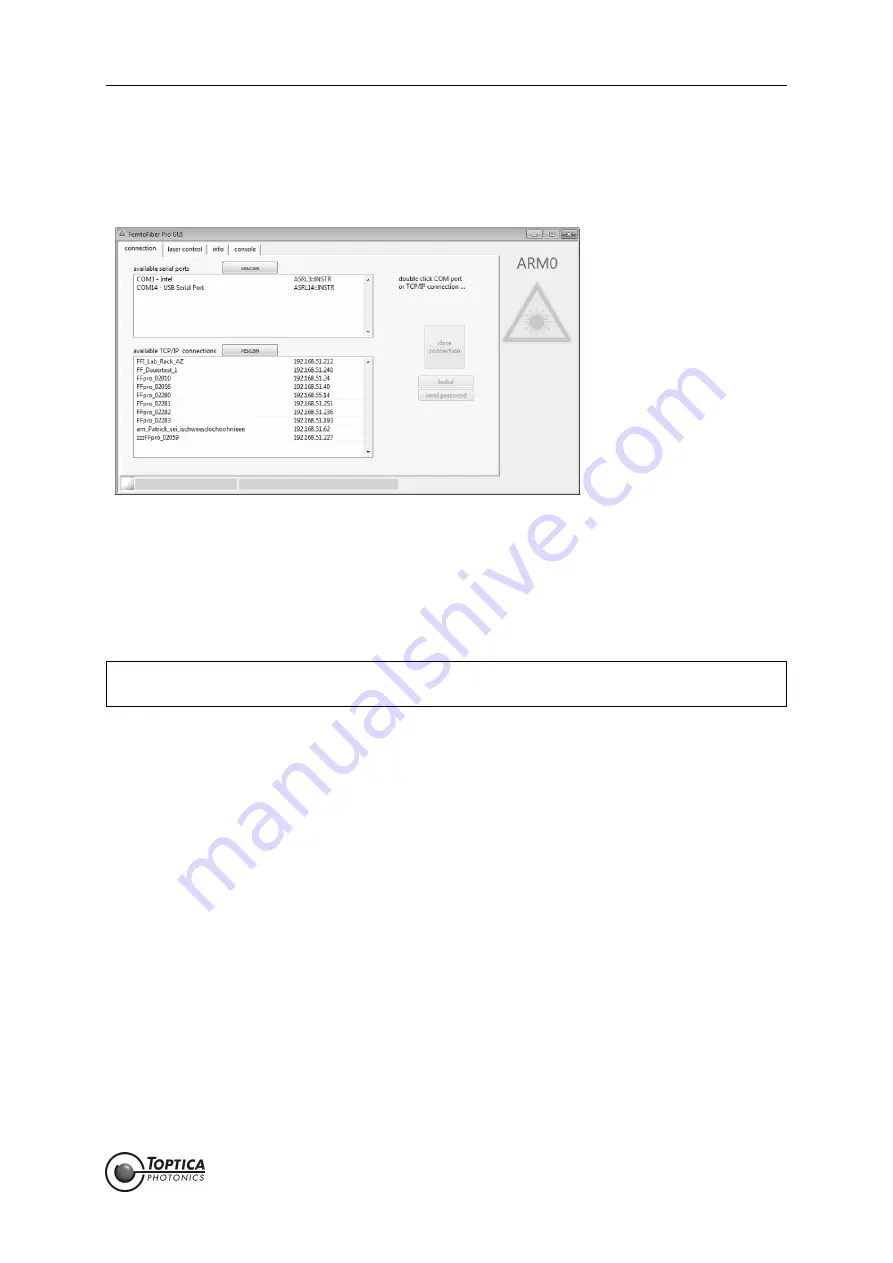
Figure 43
After starting the FemtoFiber
®
pro GUI, it will automatically scan all possible connections to your
FemtoFiber
®
pro Laser System(s). Serial and USB ports are listed in the upper boxes, laser system(s) con-
nected via TCP/IP will be displayed in the lower box (if any).
Double-click on the desired connection to activate. If the desired port is not shown, it may be re-listed
by performing a
rescan
.
After a successful connection, the list of the available ports and systems is grey-scaled and blocked.
Additionally, a green indicator at the left end of the status bar at the bottom of the screen shows that the
computer is connected with the selected laser system. Next to that, the selected port and the laser head
id (Serial number) is displayed.
As a last step, change to the
Laser Control
tab (see Figure 46) and use the
ON/OFF
buttons to start/
stop the laser emission. When the laser emits light, a yellow colored laser warning symbol is shown at the
right side of the window. For further information about the FemtoFiber
®
pro GUI operation please refer to
section 5.5.
NOTE !
For
Multi-Arm Laser Systems
please make sure that the master Control Unit is connected to
the control computer.
Summary of Contents for FemtoFiber pro IR
Page 2: ......
Page 4: ......
Page 8: ...FemtoFiber pro Laser System Status 6 9 18...
Page 99: ...6 Appendix Page 95 Status 6 9 18 6 11 Declaration of CE Conformity FemtoFiber pro SCYb...
Page 107: ......
Page 108: ......