background image


24 


3. Settings 

3.1


Function mode 

You can change and confirm the setting and the parameter in function mode.   


3.1.1


Enter and escape from the function mode


Press [FUNCTION] switch to enter and escape from the function mode.   


Enter function mode 

1


Confirm that the instrument is in HOLD status. 

Press [FUNCTION] switch for 2 seconds to enter the function mode. 


3.1.2 Setting Menu/Confirm setting data


Escape from the function mode 

  Press  [FUNCTION]  switch  to  escape from  the function mode  and  return  to  the measurement 

mode.


When escaping from the FUNCTION mode, press the [FUNCTION] switch, need not to press 

and hold the [FUNCTION] switch. 


3.1.2


Setting Menu / Confirm setting data


Each time you press [ENTER] switch in the function mode, the item in the menu change to the 

next. Press [ENTER] switch until the appropriate item appear. 

Each item is described as below; 


Average measure 

3.2.1 Average number


Measurement range 

3.2.2 Measurement range


Filter selection 

3.2.3 Filter selection


Correction factor 

3.2.4 Correction factor


Sensitivity mode 

3.2.5 Sensitivity mode


LAN parameter 

3.2.6 LAN Parameter


RS-232C parameter 

3.2.7 RS-232C parameter


Auto calibration 

3.2.8 Auto calibration


Buzzer 

3.2.9 Buzzer


Warm-up 

3.2.10 Warm-up


Memo


Summary of Contents for RD-80SA

Page 1: ...Instruction Manual Luminance Colorimeter Rev 6...

Page 2: ......

Page 3: ...asurement Do not use this instrument in dusty very damp or humid areas or in areas where corrosive gas may be generated Do not use this instrument in areas where sudden changes in temperature might oc...

Page 4: ...damage 2 1 This refers to injury such as burns electric shock or the like that does not require hospitalization or long term medical attention 2 Physical damage includes damage to the building propert...

Page 5: ...authorized AC adapter AC adapter malfunctions may result in fire or electric shock Do not disassemble the AC adapter Doing so might cause fire or electric shock Remove dust or moisture from the AC ad...

Page 6: ...lity of this instrument TOPCON TECHNOHOUSE does not assume any liability for damage that occurs due to use other than that explained in this instruction manual TOPCON TECHNOHOUSE does not assume any l...

Page 7: ...Instrument in Another System 23 3 Settings 24 3 1 Function mode 24 3 1 1 Enter and escape from the function mode 24 3 1 2 Setting Menu Confirm setting data 24 3 1 3 Menu List 25 3 2 Detail of Function...

Page 8: ...51 4 3 15 FG Command 51 4 3 16 WF_ _ _ _ Command 51 4 3 17 RF_ Command 52 4 3 18 CF_ Command 52 4 3 19 BR_ Command 52 4 3 20 DM_ Command 53 4 3 21 LIS_ Command 53 4 3 22 LIG Command 53 4 3 23 LMS_ _ _...

Page 9: ...witches or titles of screens displayed on the display Indicates a reference location in the manual Indicates another manual used as a reference Request Indicates items to keep in mind when performing...

Page 10: ...he following items have been included with your instrument If anything is missing please contact your dealer or Topcon Technohouse RD 80SA Main body 1 Objective lens cap 1 Eyepiece lens cap 1 Dedicate...

Page 11: ...C Connector Connects RS 232C cable when communicate with PC in remote mode 1 3 Preparation Analogue output connector Connects BNC cable when observing signal voltage The signal voltage is proportional...

Page 12: ...270 Depth 6 Screw hole for fixture Uses to fix the instrument to stand a base M4 0 7 4 Pitch 0 7 Appendix Request Use only specified screws when using the tripod screw and screw holes for jig attachm...

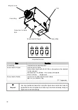
Page 13: ...r a specified number of iterations The results are averaged over specified repetitions of the measurement RUN HOLD Switch Starts Stops measurement CALIB Switch Starts calibration of the photo detector...

Page 14: ...ENTER Switch Changes the display menu and confirms new settings CHANGE Switch Changes settings in function mode and moves the cursor down digit when inputting numerical value When press this switch th...

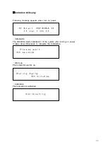
Page 15: ...appears when turn on power Initialization The RD 80SA starts initialization of the system after turning on power It takes about 60seconds to complete the initialization Warm up Photo detector warms u...

Page 16: ...ement range AT Auto MN Manual Luminance Chromaticity mode L x y Luminance Chromaticity mode L u v Tristimulus values mode X Y Z Color temperature Deviation Luminance mode Tc duv L Measurement range X2...

Page 17: ...y result in fire or electric shock Remove dust or moisture from the AC adapter plug Failure to do so might cause fire Do not plug in or unplug the AC adapter plug with wet hands Doing so might cause e...

Page 18: ...type The RS 232C signal line of the instrument is arranged according to the 9 pin D sub being used in the DOS V PC Notice The RD 80SA can connect RS 232C and LAN cable together But do not use both com...

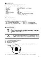
Page 19: ...LAN Parameter RS 232C communication parameter setting Refer to 3 2 7 RS 232C Parameter Object collimation Do not look at directly bright light such as the Sun and the filament lamp otherwise it cause...

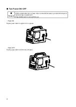
Page 20: ...after turn on power We recommend that warm up conduct 60 minute for high accuracy measurement Press RUM switch to cancel Warm up Power ON Flip the power switch to right to turn on power Power OFF Flip...

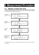
Page 21: ...ectable by pressing MODE switch during Hold status HOLD switch lighting on u v The display shows in measured data and range data in all mode until after first measurement Luminance Chromaticity mode L...

Page 22: ...in each measurement range is from 0 05V to 3V default Readout data of Luminance have relation with analogue output voltage as following table RANGE Measurable range cd Range 1 0 1 5 Range 2 0 5 15 Ra...

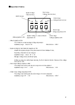
Page 23: ...tector shorten Please set the voltage from 0 3V to 0 5V Over range Voltage adjustment VR4 The voltage level which generate over range error can be adjusted Adjustable range 2 0V 3 4V Default value 3 3...

Page 24: ...ss RUN HOLD switch to start measurement Analogue output voltage is provided during RUN status Notice When over range error occur the instrument cannot provide accurate data Be sure to set appropriate...

Page 25: ...n below 2 4 Using the Instrument in Another System When using the instrument in another system such as an XY stage install it on the system using the jig attachment screws on the base of the instrumen...

Page 26: ...nt mode When escaping from the FUNCTION mode press the FUNCTION switch need not to press and hold the FUNCTION switch 3 1 2 Setting Menu Confirm setting data Each time you press ENTER switch in the fu...

Page 27: ...ge Select Auto range AUTO or Manual range MANU 3 2 2 Measurement range Filter selection Select filter from OPEN_ONLY X2_ONLY LUMINANCE ONLY Z_ONLY CHROMATICITY 3 2 3 Filter selection Correction factor...

Page 28: ...26 Auto Calibration On or Off of auto calibration of photo detector 3 2 8 Auto Calibration Buzzer On or Off buzzer sound 3 2 9 Buzzer Warm up Conducts warm up of photo detector 3 2 10 Warm up...

Page 29: ...r specified repetitions of the measurement This describe that the procedure to specify the number of measurement The number of measurement can be specified from 2 to 20 1 2 Names and functions of part...

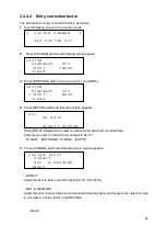
Page 30: ...ter selection 3 2 2 1 AUTO range setting There are three type of the AUTO range This described how to set each AUTO range setting 1 Current measurement range setting appears 2 Set to AUTO by pressing...

Page 31: ...s ALL RANGE The same measurement range is set to each OPEN X2 Y Z filter Press ROTATION switch to increment measurement range until appropriate measurement range EACH SELECT The measurement range are...

Page 32: ...ection Sets filter from options OPEN_ONLY No filter X2_ONLY X2 filter only LUMINANCE ONLY Y filter only Luminance measurement Z_ONLY Z filter only CHROMATICITY X2 Y Z filter Luminance Chromaticity mea...

Page 33: ...e and chromaticity value are found enter them via panel switch and measures the object The RD 80SA calculate correction factor KX KY KZ from reference data and measured value Correction factor are cal...

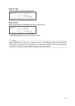
Page 34: ...try correction factor CLEAR Select this item to delete correction factor 3 2 4 4 Delete correction factor OFF Select this item to disable correction factor BACK Select this item to return to former sc...

Page 35: ...ollowing screen appears Press ROTATION switch to select correction factor data from recorded data Example we enter correction factor number to be 01 R NEXT ROTATION S PAGE SHIFT 5 Press CHANGE switch...

Page 36: ...s ROTATION switch figure is changed as follow Press SHIFT switch to move next digit 0 1 2 3 4 5 6 7 8 9 E 4 After entering data press ENTER switch to determine the entry Entry of reference data and ca...

Page 37: ...ction factor automatically and the correction factor data appear as follow Then screen return to FACTOR INPUT MENU screen Correction factor calculated by the RD 80SA R NEXT ROTATION S PAGE SHIFT FACTO...

Page 38: ...or cancel Details of items K01 Correction factor Number The RD 80SA can record ten correction factor data K01 K10 NO DATA When no correction factor is entered this message appear KX KY KZ Correction f...

Page 39: ...ection factor Press ENTER switch to return to the former screen REF01 SMP01 are shown in the upper left corner of the Reference data screen Measured data screen are related to correction factor No Cor...

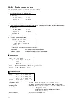
Page 40: ...n factors are deleted SELECT CLEAR Specified correction factors are deleted ALL CLEAR YES All correction factors in the memory are deleted BACK Return to the former screen SELECT CLEAR CHANGE switch C...

Page 41: ...fter selecting Press ENTER switch 3 2 6 LAN Parameter Set LAN interface parameter The procedure for setting is as follows 1 Press CHANGE switch The cursor on the IP line will blink and able to enter t...

Page 42: ...sure to turn off once after changing interface parameter 3 2 8 Auto calibration Set on or off auto calibration of photo detector The procedure for setting is as follows 1 Press CHANGE switch 2 Press...

Page 43: ...is changed 3 After selection press ENTER switch 3 2 10 Warm up Conduct the warm up to stabilize the sensitivity of photo detector Press SHIFT switch to start warm up The warm up runs for 60 minutes T...

Page 44: ...ent measured data are sent from the instrument STC Starts continuous measurement Each measured data is not sent from the instrument SPC Stops continuous measurement SMS Reads the status of continuous...

Page 45: ...Valid value range 1 10 CF_ Initializes specifying correction factor When specify 0 All correction factor data are initialized Valid value range 0 10 BR_ Sets communication speed in RS 232C 0 9600 1 1...

Page 46: ...ether in series So enough buffer are required Example When you send WHO command following 18 byte data is stored in buffer OK CR LF RD 80SA CR LF END CR LF _ means space means numerical values 4 3 1 R...

Page 47: ...n OK CR LF 4 3 4 WHO Command This command instructs the instrument to send the name of instrument PC Command RD 80SA WHO CR LF OK CR LF RD 80SA CR LF END CR LF 4 3 5 VER Command This command instructs...

Page 48: ...data Sending the command from PC to the instrument PC or PLC send character string ST 0x53 0x54 CR 0x0d LF 0x0a via LAN or RS 232C Return from the instrument to the PC The instrument returns OK CR LF...

Page 49: ...ommand But the instrument does not send measured data after completing measurement This command is used for monitoring analogue output After first measurement the instrument will send the status of co...

Page 50: ...leting first measurement 4 3 10 SMS Command Reads the latest status of continuous measurement This command is available only when the instrument is in continuous measurement mode Return value 0 Normal...

Page 51: ...VERAGE PC Command RD 80SA MV_ CR LF OK CR LF 4 3 13 AV_ Command This command sets the number of measurement for average measurement Valid value range 2 20 PC Command RD 80SA AV_ CR LF OK CR LF 4 3 14...

Page 52: ...his command sets the measurement range for each filter in RANGE EACH FO OPEN FX X2 filter FY Y filter FZ Z filter Valid value range 1 8 PC Command RD 80SA FO_ CR LF OK CR LF Above is example of FO com...

Page 53: ...ction factor number Valid value range 0 10 0 correction factor is disabled PC Command RD 80SA FG CR LF OK CR LF 12346 6 78 CR LF END CR LF 0 correction factor is disabled 4 3 20 WF_ _ _ _ Command This...

Page 54: ...F 1 689 CR LF 0 012 CR LF END CR LF 4 3 22 CF_ Command This command instructs the instrument to Initialize the correction factor data Correction factor value to be 1 0 in specify correction factor num...

Page 55: ...LF OK CR LF 4 3 25 LIS_ Command This command sets the IP address in the instrument Valid value range 192 168 0 0 192 168 255 255 PC Command RD 80SA LIS_ CR LF OK CR LF 4 3 26 LIG Command This command...

Page 56: ...80SA LMS_ CR LF OK CR LF 4 3 28 LMG Command This command the instrument to send current sub net mask Valid value range 255 255 0 0 255 255 255 255 PC Command RD 80SA LMG CR LF OK CR LF CR LF END CR LF...

Page 57: ...LF OK CR LF 50000 CR LF END CR LF 4 3 31 PMT Command This command sets sensitivity mode of photo detector Valid value range 0 INITIAL 1 USER PC Command RD 80SA PMT CR LF OK CR LF 4 3 32 ERR Command Th...

Page 58: ...number 8 Luminance cd 3 4567E 001 Luminance 9 Tristimulus values X 4 5678E 001 Tristimulus values X 10 Tristimulus values Y cd 3 4567E 001 Tristimulus values Y 11 Tristimulus values Z 2 3456E 001 Tris...

Page 59: ...instrument does not recover from the error Please contact your dealer or Topcon Technohouse Advice us of the error code the circumstance when the problem happen in details If momentary interruption o...

Page 60: ...trans error LAN trans error E0011 E0012 Under range error happen Over range error happen Check to see if the luminance of the object is within the measurable range under range error over range error E...

Page 61: ...change slightly according to the matching precision of the aperture mirror Measurement Function The measured data are represented in following unit x y L x y Chromaticity L Luminance u v L u v Chroma...

Page 62: ...ange may vary from the performance of density filter Linearity for Standard illuminant A Auto range Luminance 3 2 cd or below 2 2 cd or above Accuracy is guaranteed for measurable range only Chromatic...

Page 63: ...RH Measurement range 8 steps Auto range or Manual range Adjustment volume Over range Under range adjustment function Adjusts the over under range level Over range About 2 3 4V Default 3 3V Under rang...

Page 64: ...Analogue output voltage range About 0 3 4V Power supply Dedicated AC Adapter standard accessories AC100V 240V 50 60Hz Power consumption About 34W Operating condition Temperature 0 35 Humidity 60 RH or...

Page 65: ...0nm 500nm 600nm 700nm Relative sensitivity RD 80SA z CIE z CIE y CIE x RD 80SA y RD 80SA x Apertur e mirror Relay Lens Objective Lens Eyepiece Lens Relay Lens Filter Turret CPU A D Converter Analogue...

Page 66: ...xternal Dimension Request Use only specified screws when using the tripod screw and screw holes for jig attachment Do not tighten the screws any more than necessary Doing so might cause internal break...

Page 67: ...em Color Temperature Deviation Color temperature and deviation are calculated according to JIS Z 8725 Method for determining distribution temperature and color temperature or correlated color temperat...

Page 68: ...Local Mode This is the normal measurement status In this mode the instrument is operated by the panel switches and cannot be controlled by an external PC Remote Mode In this mode the instrument is con...

Page 69: ...house Corporation 1 Maintenance and repair parts are parts that are requires for maintaining the function of the product 2 We make utmost effort to keep maintenance and repair parts in stock for the c...

Page 70: ...ax 813 3558 4661 Inquiries regarding repairs and maintenance Tel 813 3558 2710 Fax 813 3558 3011 Luminance Colorimeter RD 80SA Instruction Manual Date of issue of 1st edition Aug 2011 6th edition Sep...

Reviews: