GR-5 Configuration
GR-5 Operator’s Manual
3-42
MINTER Configuration
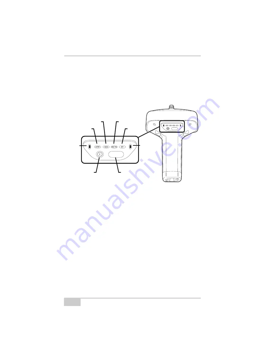
The Minimum INTERface (MINTER) consists of two keys (power
and FUNCTION) that control the receiver’s operation, four LEDs
(STAT, REC, RX/TX, and BT) that display the receiver’s operational
status, and two LEDs that display the battery status (Figure 3-38).
Figure 3-39. MINTER
The MINTER performs the following functions. For more
information on using the MINTER, see “MINTER Operation” on
page 4-8.
• Turns the receiver on or off; puts it in Sleep mode.
• Turns data recording on or off (FUNCTION button).
• Changes the receiver’s information mode.
• Shows the number of GPS (green) and GLONASS (orange)
satellites being tracked (STAT LED).
• Shows the data recording status (REC LED).
• Shows each time data is recorded to internal memory (REC
LED).
• Shows the status of post-processing mode (static or dynamic)
when performing a Post-Processing Kinematic survey with the
help of FN key (REC LED).
FUNCTION
FUNCTION
Battery
STAT
REC
RX TX
BT
Power
Button
FUNCTION
Button
Battery
Summary of Contents for GR-5
Page 1: ... PERATORlS ANUAL ...
Page 2: ......
Page 4: ...ECO 4074 ...
Page 9: ...Table of Contents P N 7010 1004 v WEEE Directive C 2 Appendix D Warranty Terms D 1 Index ...
Page 10: ...Table of Contents GR 5 Operator s Manual Notes vi ...
Page 16: ...Preface GR 5 Operator s Manual Notes xii ...
Page 18: ...Introduction GR 5 Operator s Manual 1 2 Figure 1 1 GR 5 Receiver ...
Page 44: ...Introduction GR 5 Operator s Manual Notes 1 28 ...
Page 99: ...Configuring the Receiver Using TRU P N 7010 1004 3 27 Figure 3 24 Add New Message ...
Page 121: ...MINTER Configuration P N 7010 1004 3 49 Figure 3 42 MINTER Tab ...
Page 122: ...GR 5 Configuration GR 5 Operator s Manual 3 50 ...
Page 170: ...Troubleshooting GR 5 Operator s Manual Notes 6 12 ...
Page 188: ...GR 5 Operator s Manual Notes A 18 ...
Page 192: ...GR 5 Operator s Manual Notes B 4 ...
Page 196: ...GR 5 Operator s Manual Notes D 2 ...
Page 201: ......


