Tolomatic User Guide:
IMA-S Integrated Motor Rod-Style Actuator - Stainless Steel
• 21 •
IMA-S actuators can be configured for the following feedback devices: absolute multi-turn HIPERFACE
DSL, absolute multi-turn HIPERFACE, absolute multi-turn EnDat2.2, incremental and resolver. The
selection of the feedback device is dictated by the servo drive used to operate the actuator. Each
servo drive has specific requirements for the feedback on the motor. Not all resolver-based servo
drives can use the same resolver, resolver alignment, or relative direction of resolver rotation. Not
all encoder-based servo drives can use the same encoder, encoder alignment or relative direction
of encoder rotation. Many servo drives offer software that allows the entering of parameters or
the downloading of "motor data files" that dictate how the feedback must be set up on the motor.
Tolomatic can provide many of these "data files" or the proper parameters to enter. Entering motor
parameter data to some servo drives may require assistance from the drive manufacturer.
5 .1 Feedback Commutation
When Tolomatic manufactures an IMA-S actuator, the proper feedback is selected, mounted,
commutate and tested on a drive that is known to be equivalent to the drive that the customer plans
to use for confirming proper feedback alignment and operation.
CAUTION!
In any case where it is determined that the feedback
has become misaligned, or a servo drive change is made requiring the feedback to be
commutated differently, it is recommended that Tolomatic be contacted and arrangements
made to have that procedure performed .
Feedback Type
Offset Alignment
Electrical Degree Tolerance
Hiperface
0 Degrees
+/- 5 Degrees
Hiperface DSL
0 Degrees
+/- 5 Degrees
Endat 2.2
0 Degrees
+/- 5 Degrees
Incremental Encoder
30 Degrees
+/- 5 Degrees
Resolver
90 Degrees
+/- 5 Degrees
5 .2 Feedback Commutation Details
Terminology in the industry varies from motor supplier to motor supplier. One example is in the
labeling of phases; some suppliers will reference phase R, S and T while others refer to U, V and W.
With the differences in terminology visual explanations are used for clarification purposes.
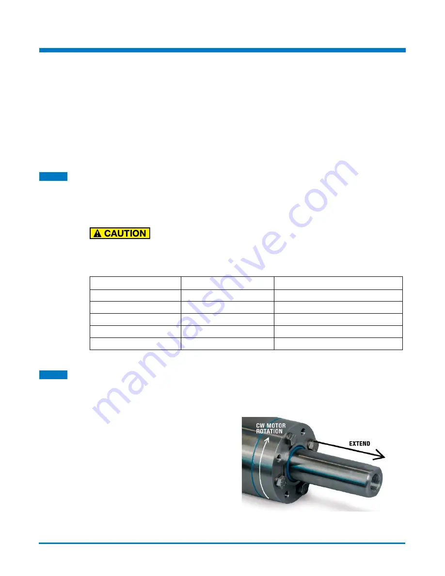
Tolomatic IMA-S motors are wired such
that as the torque generating current vector
progresses from phase U -> V -> W positive
rotation is created. Positive rotation is defined
as clockwise as viewed from the front face of
the actuator. For reference, positive rotation
will cause the thrust rod to extend.
Figure 5-1: Thrust rod movement relative to motor rotation
Electrical Installation Guidelines
5


