


20
8. CONDUCTINg A WALK-TEST
The status of the receiver’s signal reception as time shifts can be seen in the graph in real time.
Walking around in the area where the wireless microphone is used while its switch is ON in order to check for
a stable reception.
This is called a Walk-Test. The reception can be checked without checking the sound through the microphone
as was previously required.
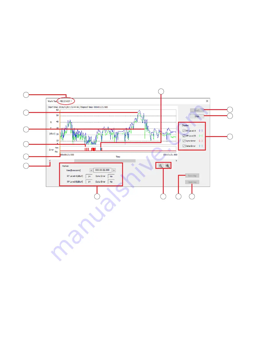
8.1. Walk-Test Screen
Note
There is only one display for the Walk-Test screen.
8
9
10
1
11
12
13
14
3
4
2
6
5
7
1. No.
Displays the receiver’s number.
2. RF level A (blue)
Displays the level of radio wave received by
Antenna A.
3. RF level B (green)
Displays the level of radio wave received by
Antenna B.
4. Sync Error (red)
Shows the synchronization status in which the
receiver is receiving signals from the microphone
and can output sound.
Sync Error can occur when the settings* of the
receiver and the microphone do not match, or the
signal that the receiver is receiving is not strong
enough.
This is not shown by default.
In order to display this, click a check in “Sync Error”
on the Display Switch (10).
* Encryption setting (ON/OFF status, ID setting) and
code setting.
5. Marker
Clicking or dragging the graph on the screen will
show the time and reception level on the Marker
display (11).
6. Scroll button
Scrolls the graph in the horizontal direction.
7. Data Error (bluish green)
Shows the data error when the signal is weak or
there is interference.
This is shown when there is a synchronization
error. This is not shown by default.
8. Start button
Starts recording Walk-Test results. Walk-Test will
continue until the Stop Test button is clicked.
After an hour, the recording will be forced to end.
9. Stop button
Ends recording of Walk-Test results.


