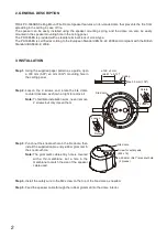
background image

2

3. INSTALLATION

 Step 1. Using the supplied paper pattern as a guide, open 

a 150 mm (5.91") ±3 mm (0.12") mounting hole in 

the ceiling panel.

Ceiling

ø150  ±3 mm

 (ø5.91" ± 0.12")

Max. 30 mm (1.18")

 Step 2. Loosen  the  2  screws  and  rotate  the  fire  dome 

counterclockwise as shown at right to remove it.
Note:    To facilitate installation work, never remove 

2 screws but only loosen them.

Fire dome

ø20.5 mm (0.81") knockout hole

(2 places)

Screw for safety wire 

(M4 x 16)

Loosen

Rotate

Loosen

Rotate

Fire dome

 Step 3. Punch out the knockout hole in the fire dome, then 

install the supplied cable entry rubber grommet in 

the knockout hole.
Note:    The grommet's cable entry hole is covered 

with  a  thin  membrane.  Cut  a  hole  in  the 

membrane to match the size of the speaker 

cable used.

 Step 4. Install the safety wire to the M4 screw on the top of the fire dome as needed.

 Step 5. Feed the speaker cable through the rubber grommet into the dome interior.

2. GENERAL DESCRIPTION

TOA's PC-1865BS Ceiling Mount Fire Dome Speaker features an iron-made dome that prevents the fire from 

spreading in the ceiling in case of fire. 

The speaker can be easily installed using the speaker mounting spring, and the dome can also be easily 

mounted in the speaker mounting hole in the ceiling panel. 

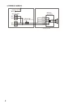
The PC-1865BS is provided with a steatite terminal block of screw type.

The PC-1865BS is certified according to the European Standard EN 54-24: 2008 and compliant with the British 

Standard BS 5839-8: 2008.

Summary of Contents for PC-1865BS

Page 1: ...sure that the bracket has no loose joints after installation to prevent accidents that could result in personal injury Avoid mounting the unit in locations exposed to constant vibration The mounting bracket can be damaged by excessive vibration potentially causing the speaker to fall which could result in personal injury To avoid electric shocks be sure to switch off the amplifier power when conne...

Page 2: ... s cable entry hole is covered with a thin membrane Cut a hole in the membrane to match the size of the speaker cable used Step 4 Install the safety wire to the M4 screw on the top of the fire dome as needed Step 5 Feed the speaker cable through the rubber grommet into the dome interior 2 GENERAL DESCRIPTION TOA s PC 1865BS Ceiling Mount Fire Dome Speaker features an iron made dome that prevents t...

Page 3: ... s input is factory preset to 1 7 kΩ When changing the input impedance detach the blank wire connected to the matching transformer and reinsert it into the desired input tap referring to the table below 3 3kΩ 1 7kΩ COM 6 7kΩ 13kΩ HOT Black COM White Matching transformer Impedance 1 7 kΩ 3 3 kΩ 6 7 kΩ 13 kΩ 100 V line 6 W 3 W 1 5 W 0 8 W 70 V line 3 W 1 5 W 0 8 W 0 4 W Step 7 Connect the earth cabl...

Page 4: ...4 4 WIRING DIAGRAM 8 Ω 13 kΩ 6 7 kΩ 3 3 kΩ 1 7 kΩ 0 COM HOT Earth COM HOT COM Matching transformer Input connector Screw connection Thermal fuse 72 ºC or 161 6 ºF Factory preset ...

Page 5: ...sions for Fixing Hole Mounting hole ø150 3 mm ø5 91 0 12 Ceiling thickness 5 25 mm 0 2 0 98 Speaker Mounting Method Spring clamp Applicable Cable Solid wire 0 8 6 mm AWG 18 10 Connection 2 Steatite connector 2 pole 1 Screw connection for Earth Finish Frame Steel plate white RAL 9016 equivalent paint Grille Steel net white RAL 9016 equivalent paint Fire dome Steel plate black paint Dimensions ø180 ...

Page 6: ......

Page 7: ......

Page 8: ...URL https www toa jp 133 01 00249 00 ...

Reviews: