6
7. CONNECTION
1
2
IN2
IN1
GND
To control signal
output terminal
1
NO
NC
COM
2
NO
NC
COM
Relay output
12 V
DC power supply
To
switching hub
To
switching hub
1
2
3
4
5
External control input
To control signal input terminal
(Closed contact)
To control signal input terminal
(Open contact)
To control signal input terminal
(Closed contact)
To control signal input terminal
(Open contact)
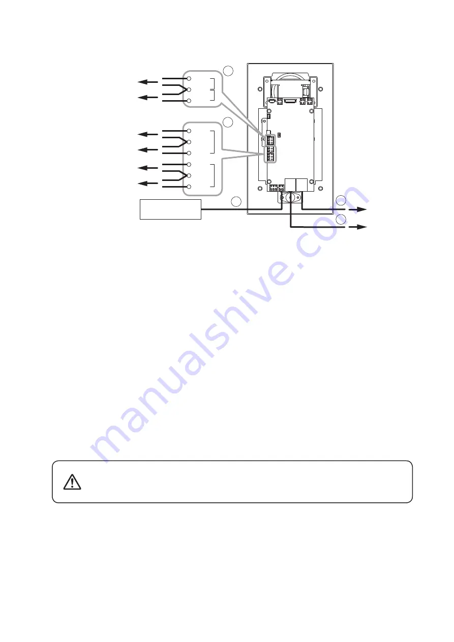
[Power supply connection]
Power is supplied from the 12 V DC power supply or the PoE-compatible switching hub.
For the power supply from the switching hub, see below "2. Ethernet connection terminal."
1. DC input terminal
Connect the 12 V DC power supply to this terminal. This terminal has no polarity. Connect the "+" and "–"
cables to each terminal.
Prepare the 12 V DC power supply separately.
Tip
If both the 12 V DC power supply and the PoE switching hub are connected, the power will be supplied from
the one that has started feeding first.
[Switching hub connection]
2. Ethernet connection terminal (PoE compatible)
Connect this terminal to the 100BASE-TX-compatible network.
Use the Ethernet RJ-45 connector for connection.
As this terminal can be connected to PoE switching hub, power can be supplied from the PoE switching hub
when this terminal is connected to it.
In this case, use the switching hub meeting the following specification.
Specification of the usable PoE switching hub: IEEE802.3af compliant
Tip
If both the 12 V DC power supply and the PoE switching hub are connected, the power will be supplied from
the one that has started feeding first.
3. Ethernet connection terminal
Connect this terminal to the 100BASE-TX-compatible network.
A PC can also be connected to this terminal when performing various settings.
Use the Ethernet RJ-45 connector for connection.
Note
This terminal is not PoE-compatible.
When power is supplied from the PoE switching hub, be sure to
use the one meeting the specified specification.
The use of the switching hub other than the specified one may
cause a fire.
CAUTION


