7
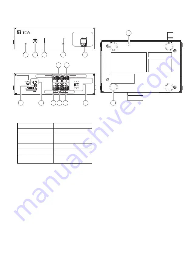
6. NOMENCLATURE AND FUNCTIONS
[Front]
1. Status indicator (green, blue, yellow, red)
Indicates the unit’s operating status.
Unit Operation
Status Indicator
System startup
Flashing green
Broadcast standby Continuously lit
green
Broadcasting
Continuously lit blue
System mute*
Flashing red
Initialization or
firmware updating
Continuously lit
yellow
* System mute is a state in which this unit is
muted by the control from the transmitting
device.
2. LINE/MIC input volume control
Adjusts the volume level of the LINE/
MIC input. Rotate this volume control
clockwise to increase the volume level and
counterclockwise to decrease it.
Set this volume not to make the LINE/MIC
input signal indicator (3) light up in red.
3. LINE/MIC input signal indicator (green,
red)
Lights green when a signal is input to LINE/
MIC input. Lights red when the input signal
level is too high.
4. Output signal indicator (green)
Lights green when a signal is outputting
from the speaker or line output.
5. Speaker output terminal (8 – 16 Ω)
Connects only with low-impedance speakers.
Tip
Amplifier rated output is as follows.
• 8 W at PoE powered, 8 Ω
• 15 W at PoE+ powered, 8 Ω
6. Line output terminal
Connects with an external amplifier etc.
and outputs the same audio as the speaker
output.
7. LINE/MIC input terminal
Connects with a microphone or sound
source device.
This can also be used as an analog audio
input when in local broadcasting mode or
alternatively as an audio input during SIP
calls, or for monitoring VMS broadcast.
Adjust with the DIP switch according to the
output level of the connected device.
8. LAN port
Connect to a PoE+ or PoE switching hub
using a LAN cable.
LINE OUT H C E
H C
1 2 3
E LINE/MIC IN
LINE
MIC
ON
OFF[PHANTOM]
0dB [PAD]
-20dB
LAN 52V
CTRL OUT
CTRL IN
LINK/ACT
H C
1 2 C
LINE/MIC IN
IP AUDIO INTERFACE IP-A1AF
OUTPUT
VOLUME SIGNAL
SIGNAL
STATUS
SPEAKER
CLASS 2 WIRING
Câblage de classe 2
8-16Ω
The figure with a removable terminal plug detached.
1 2 3
4
5
6 7
8
9
10 11 12
13
14
15
[Bottom]
[Rear]


