7
Installation
Install properly and DO NOT use this product outside the recommended
operating pressure, temperature and other specification ranges.
Improper use may result in such hazards as damage to the product or
malfunctions which may lead to serious accidents. Local regulations
may restrict the use of this product to below the conditions quoted.
CAUTION
Take measures to prevent people from coming into direct contact with
product outlets. Failure to do so may result in burns or other injury from
the discharge of fluids.
CAUTION
Installation, inspection, maintenance, repairs, disassembly, adjustment and valve
opening/closing should be carried out only by trained maintenance personnel.
1. Before installation, be sure to remove all protective seals.
2. Before installing the product, blow out the inlet piping to remove any piping scraps,
dirt and oil. Close the inlet valve after blowdown.
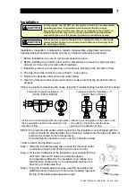
3. Install the product so that the arrow on the body is pointing in the direction of flow.
4. The trap should be inclined no more than 5° in any plane.
5. Install a condensate outlet valve and outlet piping.
6. Open the inlet and outlet valves and check to make sure that the product functions
properly.
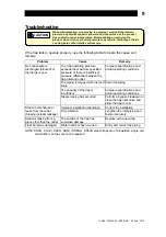
If there is a problem, determine the cause using the “Troubleshooting” section in this manual.
Tolerance Angle for Installation - 5°
(SS3N / SS5N / SS5NH)
Tolerance Angle for Installation - 5°
(SS3V / SS5V / SS5VH)
Install on a horizontal pipe with the nameplate
facing upwards and the arrow pointing in the
direction of flow
Install on a verticle pipe with the inlet on top,
the outlet on the bottom and the arrow
pointing in the direction of flow
NOTE: For products with socket weld connections the insulation cover shipped with the
product should be attached after the products is welded onto the pipe and after its
surface has cooled to room temperature.
For attaching the insulation cover, see the instruction below.
<How to attach the insulation cover>
Short tape
Long tape
Step 1. Wrap the included sealing tape around the inlet and outlet
connection at each end of the trap (3 turns for each).
Step 2. Fit the two halfshells of the insulation cover around the trap
until the 5 tabs and 5 holes are perfectly aligned.
A nameplate is affixed to the insulation cover. Make sure
that direction of the arrow on the nameplate matches the
direction of condensate flow.
Step 3. Using the included aluminum tape, seal the area where the
halfshells meet. Then wrap 3 more turns of sealing tape over
the top of the sealing tape applied in step 1.
172-65119MAJ-03 (SS3/SS5) 25 Feb 2014

