42
Embedded Modules
© Tibbo Technology Inc.
Therefore, your battery-based backup circuit should be designed in a way that does
not drain the battery while the Vcc is applied.
The RTC will continue to function with backup power on the VCCB pin as low as
2.2V. Make sure that the voltage on this pin does not exceed 3.3V. Failure to
observe this limit may cause permanent damage to the EM1000.
Your Tibbo BASIC/C application can access the RTC through the RTC (rtc.) object,
which is documented in the TIDE, TiOS, Tibbo BASIC, and Tibbo C Manual.
*With the right application, that is.
4.2.2.8
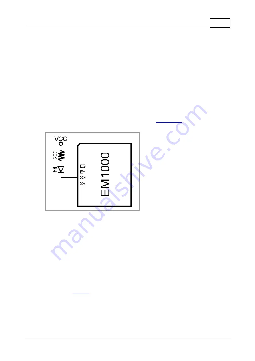
LED Lines
The EM1000 has four LED control lines -- SG, SR, EG, and EY. All lines have the
same internal structure and the LEDs should be connected to these lines as shown
on the schematic diagram below. Maximum load for each line is 10mA.
Further information on status LEDs can be found in
Your Tibbo BASIC/C application can control red and green status LEDs, as well as up
to four externally connected LED pairs through the pattern (pat.) object, which is
documented in the TIDE, TiOS, Tibbo BASIC, and Tibbo C Manual.
4.2.2.9
Power, Reset, PLL Control, and Mode Selection Lines
The EM1000 should be powered from a stabilized DC power supply with nominal
output voltage of 3.3V (+/- 5% tolerance). This power should be applied to the pin
#60. "-A" modification of the EM1000 has the second VCC pin -- #72. To prevent
"current loops", only use either pin #60, or pin #72 to supply the power to the
device.
Current consumption of the EM1000 is approximately 230mA (PLL on, 100BaseT
mode). This does not include the power consumption of the wireless add-on module,
such as the
. The slave module, depending on its type, can add significantly
to the power consumed by the EM1000. Therefore, providing an adequate power
supply is very important -- poorly built circuit may affect EM1000 operation. We
recommend that you use a switching power supply. One (but not the only) example
of such circuit is shown below.


