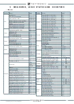


INSTALLATION
371
6.4 RATED
I
n
AND
I
en
SETTINGS
The values of the relay rated current can be set to 1 A or 5 A via ThyVisor sw; parameters are avai-
lable in the
Set \ Base
menu.
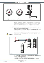
6.5
LED COMMISSIONING
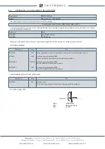
Following indicator LEDs are available on the front panel:
• LED ON (green): if no diagnostic anomalies are detected, the green LED is turned ON while any
fault is highlighted by flashing
• LED START (yellow) committed for start information of any protective functions
• LED TRIP (red) committed for trip information of any protective functions
• LED 1...16 (Programmable RED, GREEN, YELLOW) are freely assignable from the user to any
protective and/or control functions.
A relevant description can be associated with each Led via ThyVisor and by Display Led Label
key presents on touch-screen keyboard it is possible recall all Led descriptions.
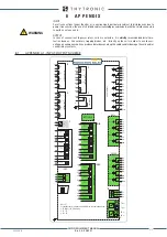
6.6
FINAL OPERATIONS
Before energizing the electric board, it is advisable to check that:
• The auxiliary voltage must be comprise in XMR-x relays operative range
• The rated current (1 A or 5 A) of the line CT’s corresponds to XMR-x relays set values
• All wirings are correct
• All screws are tightly screwed
LED1-1...LED1-16
User Programmable
ON & Diagnostic
Start
Trip
OPEN CB
CLOSED CB
ON & Diagnostic
Start
Trip
LOCAL
REMOTE
f1
÷
f10
Accelerator keys
Display LED Label
LOCAL
REMOTE
VISUAL INDICATION
XMR-D EQUIPMENT MANUAL
Ed. 2.9 - 02/2021


