

130
130
NC20 - Manual - 01 - 2015
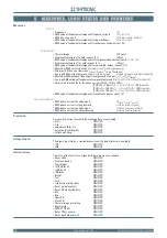
MEASURES, LOGIC STATES AND COUNTERS
5 M E A S U R E S , L O G I C S T A T E S A N D C O U N T E R S
5 M E A S U R E S , L O G I C S T A T E S A N D C O U N T E R S
Measures
Direct
Frequency
(
f
)
RMS value of fundamental component for phase currents
(
I
L1
,
I
L 2
,
I
L 3
)
RMS phase currents
(
I
L1RMS
,
I
L 2RMS
,
I
L 3RMS
)
RMS value of fundamental component for input voltages
(
U
L1
,
U
L 2
,
U
L 3
)
RMS value of fundamental component for unbalance neutral current (
I
N
)
Calculated
Thermal image
(
DTheta
)
Displacement angle of
I
N
with respect to
I
L1
(
Phi
N
)
RMS value of fundamental component for compensated neutral current (
I
NC
=
I
N
-
I
C
)
Displacement angle of
I
NC
with respect to
I
L1
(
Phi
NC
)
RMS value of fundamental component for calculated residual current (
I
EC
)
Maximum RMS current between
I
L1RMS
-
I
L 2RMS
-
I
L 3RMS
(
I
LMAX-RMS
)
Minimum RMS current between
I
L1RMS
-
I
L 2RMS
-
I
L 3RMS
(
I
LMIN-RMS
)
Average RMS current between
I
L1RMS
-
I
L 2RMS
-
I
L 3RMS
[
I
L-RMS
= (
I
L1RMS
+
I
L2RMS
+
I
L3RMS
)/3]
Maximum RMS voltage of fundamental component between
U
L1
-
U
L 2
-
U
L 3
(
U
LMAX
)
Average RMS voltage of fundamental component between
U
L1
-
U
L 2
-
U
L 3
[
U
L
= (
U
L1
+
U
L 2
+
U
L 3
)/3]
Harmonic distortion factor for phase currents
THD
L1
-
THD
L 2
-
THD
L 3
[
THD
L1
% = 100∙√(
I
L1
2
+
...
+
I
L1-11th
2
)/
I
L1
] = 100∙
I
L1RMS
/
I
L1
[
THD
L 2
% = 100∙√(
I
L 2
2
+
...
+
I
L 2-11th
2
)/
I
L 2
] = 100∙
I
L 2RMS
/
I
L1
[
THD
L 3
% = 100∙√(
I
L 2
2
+
...
+
I
L 3-11th
2
)/
I
L 3
] = 100∙
I
L 3RMS
/
I
L1
RMS value of fundamental component for unbalance phase current (
I
2
)
Demand phase
RMS phase currents fi xed demand
(
I
L1FIX
,
I
L 2FIX
,
I
L 3FIX
)
RMS phase currents rolling demand
(
I
L1ROL
,
I
L 2ROL
,
I
L 3ROL
)
RMS phase currents peak demand
(
I
L1MA X
,
I
L 2MA X
,
I
L 3MA X
)
RMS phase currents minimum demand
(
I
L1MIN
,
I
L 2MIN
,
I
L 3MIN
)
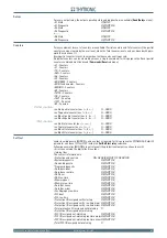
Protection
For each protection threshold, the following data are available:
Start
ON/OFF
Trip
ON/OFF
Logic block (Block1)
ON/OFF
Selective block (Block2)
ON/OFF
Cold Load Pickup
ON/OFF
Delayed inputs
The binary input states, acquired downstream the delay timers are available:
IN1
ON/OFF
IN2
ON/OFF
Internal states
The state of the functions assigned to binary inputs are available:
Reset LEDs
ON/OFF
Profi le selection
ON/OFF
Fault trigger
ON/OFF
IE /IPh Block2
ON/OFF
IPh Block2
ON/OFF
IE Block2
ON/OFF
Block1
ON/OFF
Tcs1
ON/OFF
Tcs2
ON/OFF
Trip External protections
ON/OFF
Reset partial counters
ON/OFF
Reset CB monitoring data
ON/OFF
52a
ON/OFF
52b
ON/OFF
Open CB
ON/OFF
Close CB
ON/OFF
Thermal image presetting
ON/OFF
Remote trip
ON/OFF
MCB VT OPEN
ON/OFF
Reset TDcnt counter
ON/OFF
Reset discharge timer tD
ON/OFF
•
•
•
•
•
•
•
•
•
•
•
•
•
•
•
•
•
•
•
•
•
•
•
•
•
•
•
•
•
•
•
•
•
•
•
•
•
•
•
•
•
•
•
•
•
•
•
•
•