background image

3-7

3  Installation 

Battery Charger

0048

3.7  FLOAT CHARGE VOLTAGE ADJUSTMENT

1. 

Connect a voltmeter to the “- B” terminals X9 and X10 located to the left on the 


connection area.

2. 

Connect the mains to the unit.

3. 

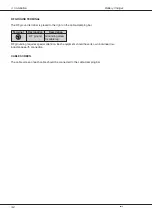
Adjust the potentiometer R48 located between the two aluminium covers (refer to the figure 


below) until the charge voltage prescribed by the battery manufacturer is read on the 


voltmeter (range 26.6V DC - 28.8V DC).

4. 

Disconnect all instruments.

5. 

Disconnect the mains to the unit.

6. 

Connect the battery to the “- B” terminals located to the left on the connection area.

7. 

Connect the mains to the unit.

R48

20A

-

+

-

+

-

+

10A

10A

10A

10A

10A

DC 1

10A

+

-

20A

30A

+

-

BATTERY

CHARGE

X4

X5

X9

X10

X2

X1

FLOAT

MAIN

AC

ALR

LIGHT

AC

ALR

VBAT-

DC 2

DC 3

VBAT+

N

L

X14

X13

X15

37726

230V/8AT

F13

115V/15AT

F12

Summary of Contents for CH2410

Page 1: ...Battery Charger T e c h n i c a l M a n u a l Valid for CH4656 CH4666 CH2410...

Page 2: ...the accompanying documentation is disclaimed The information in this quick guide is furnished for informational use only is subject to change without notice may contain errors or inaccuracies and repr...

Page 3: ...F OPERATION 2 1 3 INSTALLATION 3 1 3 1 OUTLINE AND DIMENSIONS 3 1 3 2 MOUNTING POSSIBILITIES 3 1 3 3 INSTALLATION WIRING 3 2 3 4 BLOCK DIAGRAM 3 3 3 5 AC SUPPLY VOLTAGE SETTING 3 4 3 6 CONNECTIONS 3 4...

Page 4: ......

Page 5: ...uipment if battery and Battery Charger is used in an uninterruptible power supply UPS configuration Furthermore the Battery Charger includes the following features 115V 230V selectable input Encapsula...

Page 6: ...cteristic Battery type Lead acid open or sealed Nominal battery capacity 20 120 Ah Nominal charging time 10 hours to 80 capacity 120 Ah battery Battery monitoring Protected output AC Mains Alarm outpu...

Page 7: ...a constant voltage generator to maintain a constant voltage to the battery Four DC outputs are connected directly to the battery making it possible to use the Battery Charger and the battery in an uni...

Page 8: ...2 2 2 Technical Description Battery Charger 0048...

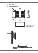
Page 9: ...3 1 OUTLINE AND DIMENSIONS 0048 37669 4 screws M5 x 12 4 screws M5 x 12 9 2 MOUNTING POSSIBILLITIES 370mm Mounting 4 holes 7mm 37670 160mm 260mm 331mm 110mm Cable entry in bottom 350mm 1 1 2 1 1 Spac...

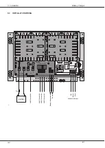
Page 10: ...A 20A 30A BATTERY CHARGE X4 X5 X9 X10 X2 X1 FLOAT MAIN AC ALR LIGHT AC ALR VBAT DC 2 DC 3 VBAT N L X14 X13 X15 Battery voltage monitor AC alarm Line Neutral Earth 37593 Fuse 230 115V AC input 28V DC f...

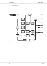
Page 11: ...TIFIER FILTER CURRENT TRAFO PUSH PULL STAGE CURRENT FEEDBACK DRIVER STAGE PWM SLOPE COMP POWER TRAFO OUTPUT RECTIFIER FILTER AUXILLARY SUPPLY OPTO OTP OVP OPTO BATTERY MONITOR 37673 AC ALR VBAT BATTER...

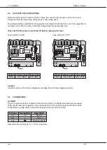
Page 12: ...ion Incorrect setting of the mains voltage may damage the AC Power Supply assembly 3 6 CONNECTIONS AC INPUT The AC supply leads are connected to the terminal block as indicated Screened power supply c...

Page 13: ...voltage Terminal Designation Description X5 5 DC 3 28V DC or Battery X5 6 DC 3 voltage Terminal Designation Description X4 1 VBAT Protected Battery X4 2 VBAT monitor output BATTERY The battery is conn...

Page 14: ...cable clamping bar RF grounding requires special attention Each equipment should have its own individual low inductance earth connection CABLE SCREEN The cable screen of each cable should be connecte...

Page 15: ...e figure below until the charge voltage prescribed by the battery manufacturer is read on the voltmeter range 26 6V DC 28 8V DC 4 Disconnect all instruments 5 Disconnect the mains to the unit 6 Connec...

Page 16: ...3 8 3 Installation Battery Charger 0048...

Page 17: ...4 1 4 Schematic Diagram and Component Location Battery Charger 4 SCHEMATIC DIAGRAM AND COMPONENT LOCATION 4 1 POWER SUPPLY UNIT SCHEMATIC DIAGRAM This diagram is valid for PCB 36550D 0048...

Page 18: ...Diagram and Component Location Battery Charger COMPONENT LOCATION Not mounted components C8 C37 C40 K1 R14 R15 R20 R36 R41 R42 R43 R56 V15 V27 V34 Seen from komponent side with upper side tracks PCB...

Page 19: ...5104 78104 11 136 C34 CAPACITOR CLASS Y2 22nF 20 250VAC PHILIPS 2222 336 60223 61223 13 908 C35 CAPACITOR MKT 100nF 10 63VDC BC Components 2222 370 75104 78104 11 136 C36 CAPACITOR CERAMIC 1n0F 10 CL2...

Page 20: ...F06P 501 M 58324701 R49 RESISTOR PMF 12 OHM 5 2W PHILIPS 2322 194 13129 04 136 R50 RESISTOR MF 100 OHM 5 0 33W PHILIPS 2322 187 73101 02 448 R52 RESISTOR MF 5R11 1 0 25W PHILIPS 2322 157 15118 25118 0...

Page 21: ...067 V40 TRANSISTOR AF BC547B NPN TO 92 PHILIPS BC547B 126 28 067 V41 DIODE LIGHT EMITTING GREEN 4mCd 10mA TEMIC TLHG 4401 AS 12 Z 21Z 82300014 V42 DIODE LIGHT EMITTING GREEN 4mCd 10mA TEMIC TLHG 4401...

Page 22: ...5 4 5 Parts List Battery Charger 0048...

Page 23: ...r 230V 1 45 519 Fuse 15AT for 115V 2 45 630 Fuse auto blade 10A 2 45 663 Fuse auto blade 20A 2 45 665 Fuse auto blade 30A 1 45 667 Screw M4x30 11 87 363 Screw M4x20 17 87 359 Screw M5x12 5 87 453 Shee...

Page 24: ...6 2 6 Accessories Included Battery Charger 0048...

Page 25: ......

Page 26: ...T e c h n i c a l M a n u a l Thrane Thrane Denmark info thrane com www thrane com...

Reviews: