© 2007 - 2018 Thorlabs
86
Wavefront Sensor
7.2 Troubleshooting
·
No Wavefront Sensor found after software start
Note
If the Wavefront Sensor is connected to a different USB port of the PC than before, the
Wavefront Sensor driver must be installed for this USB port, too. Wait a few seconds until
the driver is installed successfully and the WFS is ready to use. See also
.
Ø
Check if the Wavefront Sensor is connected to the USB port of the PC using the included
USB cable.
Ø
Make sure that WFS30 and WFS40 devices are connected to a USB 3.0 port on your
computer. USB3.0 ports can be recognized by their blue plastic insert. Additionally, they
are marked with the USB3
logo.
The
at the back of the Wavefront Sensor indicates the instrument state:
- LED = off
USB cable or USB port is defective
- LED = red
WFS20: DC power supply is missing.
WFS30 / WFS40: Sensor is not recognized by the Windows system; install
the Wavefront Sensor drivers (see
)
- LED = green Wavefront Sensor is properly installed and ready for operation
Ø
Was the Wavefront Sensor software installed completely?
Ø
Be sure to have administrative privileges on your computer to install software. Contact
your system administrator in case of trouble.
Ø
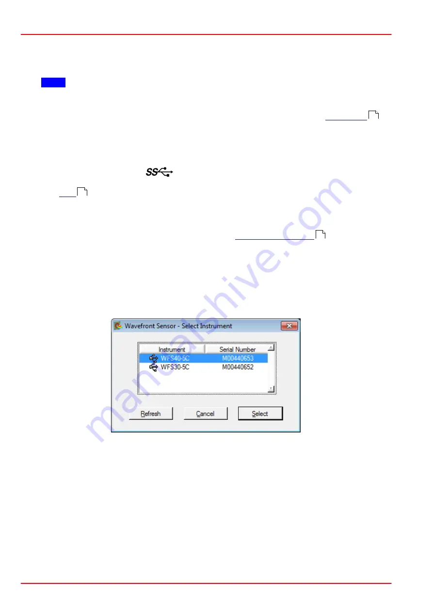
Click the 'Refresh' button in the 'Select Instrument' dialog. It will take a few seconds to rec-
ognize the instrument.
For verification purposes, check the USB controller branch of the Device Manager in the
Control Panel. If properly installed, the Wavefront Sensor hardware appears in the list as
shown on the next page:
16
15
14
Summary of Contents for WFS20-14AR
Page 2: ...Copyright 2007 2018 Thorlabs Version Date 5 0 19 Jul 2018...
Page 15: ...2007 2018 Thorlabs 3 Coordinate Definitions 13 Wavefront Graph...
Page 106: ...2007 2018 Thorlabs 104 Wavefront Sensor Selectable camera image sizes for WFS40 Normal Mode...
Page 107: ...2007 2018 Thorlabs 8 Appendix 105 Selectable camera image sizes for WFS40 sub2 Mode...
Page 123: ...2007 2018 Thorlabs 8 Appendix 121 8 9 2 Drawing WFS20 5C...
Page 124: ...2007 2018 Thorlabs 122 Wavefront Sensor 8 9 3 Drawing WFS20 5C M...
Page 125: ...2007 2018 Thorlabs 8 Appendix 123 8 9 4 Drawing WFS20 7AR...
Page 126: ...2007 2018 Thorlabs 124 Wavefront Sensor 8 9 5 Drawing WFS20 7AR M...
Page 127: ...2007 2018 Thorlabs 8 Appendix 125 8 9 6 Drawing WFS20 14AR...
Page 128: ...2007 2018 Thorlabs 126 Wavefront Sensor 8 9 7 Drawing WFS20 14AR M...
Page 129: ...2007 2018 Thorlabs 8 Appendix 127 8 9 8 Drawing WFS20 Control Box...
Page 130: ...2007 2018 Thorlabs 128 Wavefront Sensor 8 9 9 Drawing WFS30 5C...
Page 131: ...2007 2018 Thorlabs 8 Appendix 129 8 9 10 Drawing WFS30 5C M...
Page 132: ...2007 2018 Thorlabs 130 Wavefront Sensor 8 9 11 Drawing WFS30 7AR...
Page 133: ...2007 2018 Thorlabs 8 Appendix 131 8 9 12 Drawing WFS30 7AR M...
Page 134: ...2007 2018 Thorlabs 132 Wavefront Sensor 8 9 13 Drawing WFS30 14AR...
Page 135: ...2007 2018 Thorlabs 8 Appendix 133 8 9 14 Drawing WFS30 14AR M...
Page 136: ...2007 2018 Thorlabs 134 Wavefront Sensor 8 9 15 Drawing WFS40 5C...
Page 137: ...2007 2018 Thorlabs 8 Appendix 135 8 9 16 Drawing WFS40 5C M...
Page 138: ...2007 2018 Thorlabs 136 Wavefront Sensor 8 9 17 Drawing WFS40 7AR...
Page 139: ...2007 2018 Thorlabs 8 Appendix 137 8 9 18 Drawing WFS40 7AR M...
Page 140: ...2007 2018 Thorlabs 138 Wavefront Sensor 8 9 19 Drawing WFS40 14AR...
Page 141: ...2007 2018 Thorlabs 8 Appendix 139 8 9 20 Drawing WFS40 14AR M...
Page 144: ...2007 2018 Thorlabs 142 Wavefront Sensor 8 11 Certifications and Compliances...
Page 145: ...2007 2018 Thorlabs 8 Appendix 143...
Page 153: ...www thorlabs com...


