Thermoelectric Temperature Controller
TED200COperation Manual
2015
Page 1: ...Thermoelectric Temperature Controller TED200C Operation Manual 2015...
Page 2: ...Version Date 3 3 02 Jul 2015 Copyright 2015 Thorlabs...
Page 3: ...Connecting a temperature sensor 14 3 1 5 Analog Temperature Tuning Input 14 3 1 6 Analog Temperature Output 15 3 2 Operation 15 3 2 1 Setting the TEC current limit 16 3 2 2 Adjusting Temperature Contr...
Page 4: ...ternational partners are looking forward to hearing from you Thorlabs GmbH Warning Sections marked by this symbol explain dangers that might result in personal injury or death Always read the associat...
Page 5: ...EC current is activated The set value of the temperature can be changed with a knob at the front panel or via an analog input at the rear panel For monitoring purposes an DC voltage proportional to th...
Page 6: ...ion cables only Only with written consent from Thorlabs may changes to single components be carried out or components not supplied by Thorlabs be used This precision device is only serviceable if prop...
Page 7: ...accordance with the instructions may cause harmful interference to radio communications However there is no guarantee that interference will not occur in a particular installation If this equipment do...
Page 8: ...unt Note The cable should not be manipulated as it serves multiple devices and therefore does not have the standard pin assignment as described for TED200C Laser diode mounts for different laser diode...
Page 9: ...C controller 2 1 power cord connector according to ordering country 3 1 operation manual 4 1 connection cable CAB420 15 2 2 Preparation Prior to operate a TED200C controller check if the set line volt...
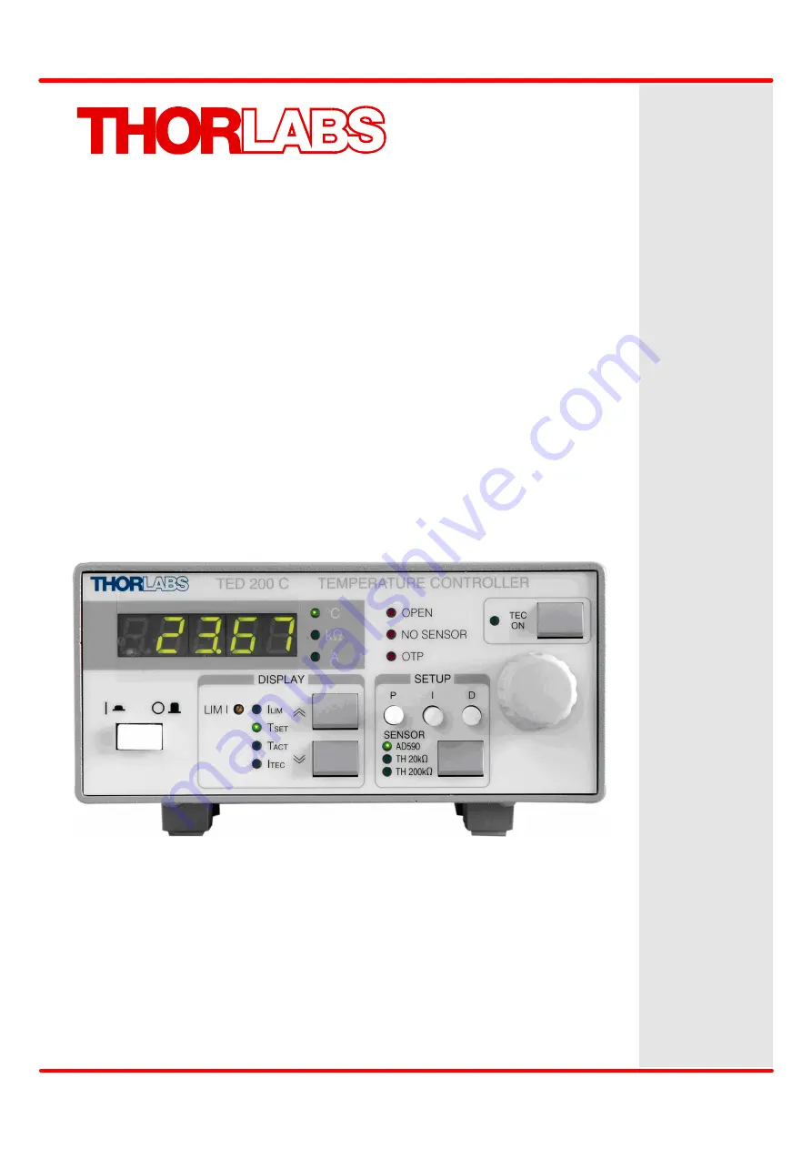
Page 10: ...limit F13 LED TACT Display shows the actual temperature resistance F14 LED ITEC Display shows the TEC current F15 LED TSET Display shows the set temperature resistance F16 LED ILIM Display shows the c...
Page 11: ...Prior to switch on your TED200C controller please make sure that the line voltage setting corresponds to your mains voltage Mismatching may lead to damage of the controller Turn the unit on by pressin...
Page 12: ...not be manipulated as it serves multiple devices and therefore does not have the standard pin assignment as described for TED200C If a Thorlabs laser mount TCLDM9 or LDM21 is used in addition the pol...
Page 13: ...g knob By pressing the key ON switch on the TED200C output current The LED ON F8 lights up Switch the LED display to TACT If the TEC module is connected with correct polarity the difference between th...
Page 14: ...PUT R5 at the rear of the TED200C depending on the used sensor type Note If LM135 LM335 is used as temperature sensor select AD590 key F25 The LED AD590 F19 lights up Thermistor A thermistor is a resi...
Page 15: ...ce an output current linearly proportional to the absolute temperature These devices act as current source delivering 1 A K within a wide supply voltage range They are calibrated to 298 2 A output cur...
Page 16: ...the temperature set value 1 Hz are possible via the analog control input TUNE IN The actual temperature TACT can be observed at the temperature monitor output CTL OUT R2 3 1 6 Analog Temperature Outpu...
Page 17: ...e C the resistance is set kW If an AD590 AD592 or LM135 LM335 is used as temperature sensor the set temperature is entered in C Switch on the TEC current output by pressing key ON F9 The LED ON F8 lig...
Page 18: ...east one second to switch off the I share The sensor LED F19 F20 F21 is flashing to indicate the I share off state 4 Set the temperature TSET to a value around room temperature and switch on the TEC c...
Page 19: ...ime with at most one overshoot 3 2 3 Over Temperature Protection The TED200C controllers come with an internal over temperature protection If the internal heat sink is overheated the output of the con...
Page 20: ...ages of 100 V 15 10 90 V 115 V 115 V 15 10 104 V 132 V 230 V 15 10 207 V 264 V line frequency 50 60 Hz The line voltage setting can be changed from the rear without opening the unit 1 Turn off the con...
Page 21: ...pressing its plastic retainers with the aid of a small screwdriver The retainers are located on the right and left side of the holder and must be pressed towards the center 3 Replace the defective fus...
Page 22: ...onding connections and polarities of the temperature sensor Select the corresponding temperature sensor by pressing key F25 Adjust the right set value for TSET q After pressing TEC ON the unit beeps a...
Page 23: ...ability 24 hours 3 0 5 W 5 W IC Sensors Transducers Supported Sensors AD590 AD592 LM135 LM335 Control Range with AD590 LM135 45 C to 145 C Control Range with AD592 25 C to 105 C Control Range with LM3...
Page 24: ...o 31 C decreasing to 50 at 40 C Pollution Degree Indoor Use only 2 Operation Altitude 2000 m Warm up Time for Rated Accuracy 10 min Dimensions W x H x D w o Operating Elements with Operating Elements...
Page 25: ...2015 Thorlabs 5 Appendix 23 5 2 Declaration of Conformity...
Page 26: ...ftware determined by Thorlabs for this unit to operate fault free provided that they are handled according to our requirements However Thorlabs does not warrant a fault free and uninterrupted operatio...
Page 27: ...this product In no event shall any liability exceed the purchase price of the product Please note that the content of this User Manual is neither part of any previous or existing agreement promise rep...
Page 28: ...e does not refer to other Thorlabs products such as pure OEM products that means assemblies to be built into a unit by the user e g OEM laser driver cards components mechanics and optics left over par...
Page 29: ...orlabs Sweden AB M lndalsv gen 3 412 63 G teborg Sweden Tel 46 31 733 30 00 Fax 46 31 703 40 45 www thorlabs com Email scandinavia thorlabs com France Thorlabs SAS 109 rue des C tes 78600 Maisons Laff...