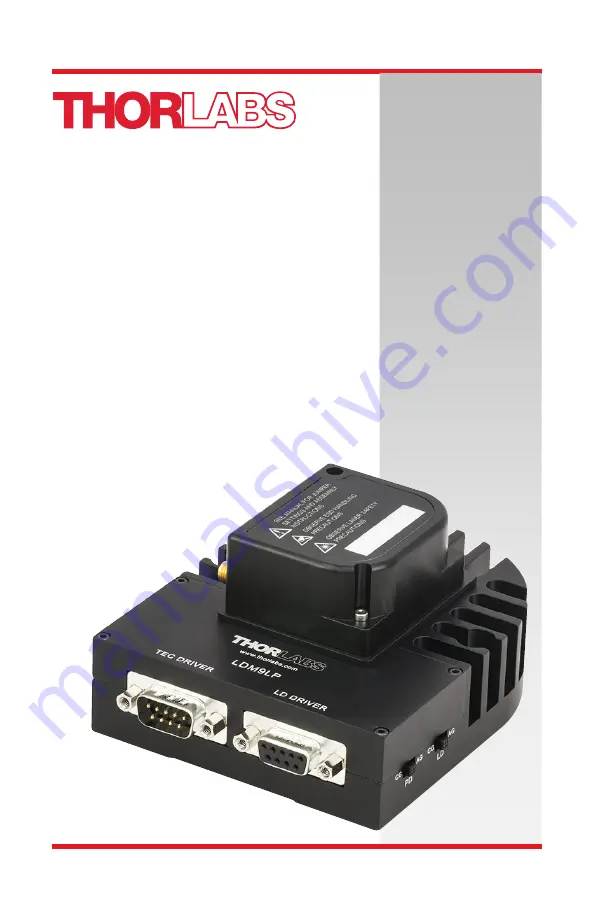
LDM9LP Pigtailed Laser Mount Operating Manual
Page 1: ...LDM9LP Pigtailed Laser Mount Operating Manual...
Page 2: ...nt Controller Connection 11 4 5 Using a Third Party Laser Controller 12 4 6 TEC Controller Connection 13 4 7 TEC Lockout and Ground Jumpers 14 Operation 15 5 1 General 15 5 2 RF Modulation 15 5 3 Stat...
Page 3: ...ription Direct Current Alternating Current Both Direct and Alternating Current Earth Ground Terminal Protective Conductor Terminal Frame or Chassis Terminal Equipotentiality On Supply Off Supply In Po...
Page 4: ...ount Chapter 2 Safety Page 2 TTN027954 D02 Safety WARNING This unit must not be operated in explosive environments WARNING Avoid Exposure Laser Radiation Emitted from apertures WARNING Observe ESD Han...
Page 5: ...diode mounts rely on contact between the diode and the mount s cold plate for heat transfer Pigtailed laser diodes are often recessed in the pigtail s housing offering poor contact with the cold plate...
Page 6: ...4 TTN027954 D02 LDM9LP Contents Pigtail Mount 1 5mm Hex Key Operating Manual Supported Pin Style Style A Case LD PD LD PD LD PD LD PD Case Case Case Style B Style C Style D LD Case Style E LD Case Sty...
Page 7: ...eral 1 Remove the two M2 screws from the protection cover and remove the cover 2 Remove the four M2 screws that fix the upper cooler shell and remove the upper shell 3 Remove the two M2 screws fixing...
Page 8: ...in configuration being used For pin codes A B C D E or H set the STYLE jumper to the lower two pins For pin code G set the jumper to the upper two pins 6 The BYPASS jumper should be set only if the la...
Page 9: ...DM9LP according to the diagram below Polarity Switch Settings Style A Case LD PD LD PD LD PD LD Case Case Case Style B LD PD Case Style C LD Case Style G Style D Style E LD Case Style H LD LD LD PD LD...
Page 10: ...hread the two M2 socket head screws into the pigtail flange securing it to the mounting flange Next replace the upper cooler shell and tighten the four M2 socket head screws Lastly reattach the protec...
Page 11: ...mon pin will be inserted into either of the holes marked G below Insert the isolated laser pin in the position marked LD The isolated photodiode should now be in the position marked PD Socket Pin Diag...
Page 12: ...o clock position anode or cathode The mount will tie the laser and photodiode pins located at 9 o clock and 3 o clock together and also to ground By noting which polarity pins are inserted in the sock...
Page 13: ...horlabs controllers and ensure that the controllers cannot be connected incorrectly Additionally these controllers have built in protection circuitry that protects the laser when not in use The nomenc...
Page 14: ...pin grounds the anode of the laser diode and photodiode 4 Photodiode Anode This pin is connected to the 6 o clock pin on the laser socket when the PD polarity switch is set to CG cathode grounded It...
Page 15: ...ace to the laser mount Please refer to the table below for connections TEC Controller DB9 Male Connection TEC Pin Signal Description 1 TEC Lockout This pin is connected to the anode of the photo relay...
Page 16: ...with the TEC Lockout feature bypassed To enable the TEC Lockout simply remove the cover of the unit and remove the blue jumper from the JMP1 header The jumper can be placed on one of the other header...
Page 17: ...z to beyond 1 GHz This is a 50 input that is AC coupled directly to the laser through the Bias T network To calculate the desired RF power to modulate the laser determine the amount of modulating curr...
Page 18: ...ide the LDM9LP case see 4 7 Connect a resistor to LD Interface DB9 Pin 1 appropriately sized to limit the current into Pin 1 to between 5 and 10 mA The driver side of this resistor should be connected...
Page 19: ...eature then you can leave the shorting device installed and the unit will operate normally as described in the procedures in this manual If you wish to make use of the interlock feature you will need...
Page 20: ...Try adjusting the temperature to shift the laser diode to a more stable operating point The LDC Series Laser Driver Indicates an Open Circuit Alarm When You Try to Enable the Laser Possible Solution D...
Page 21: ...aximum TEC Current 4 5 A Maximum TEC Voltage 3 0 V TEC Heating Cooling Capacity 7 W Mounted to 12 x 12 Breadboard Typical Temperature Range LD Dependent 0 to 70 C 10 to 70 C Mounted on 12 x 12 Breadbo...
Page 22: ...es below 200 kHz the RF modulator should be connected to the LD controller Figure 9 shows the performance of Thorlabs LDC202C and ITC4005 when used with the LDM9LP and RF modulation Above 200 kHz the...
Page 23: ...Pigtailed Laser Mount Chapter 8 Specifications Rev C September 5 2018 Page 21 RF Modulation Through SMA Connector on LDM9LP...
Page 24: ...nce with temperature predestines a NTC for temperature measurements The diagram above shows the typical curve for a 10k thermistor Usually its nominal resistance is referenced to 25 C The dependency o...
Page 25: ...13 9 mm 3 50 88 9 mm 2 11 53 7 mm 1 13 28 6 mm 2 05 52 0 mm 2 25 57 2 mm RF Input SMA Connector Interlock 2 5 mm Phone Jack Input LD ON Indicator LED DB9 TEC Interface Connector Laser Pigtail Protecti...
Page 26: ...products such as Pure OEM products that means assemblies to be built into a unit by the user e g OEM laser driver cards Components Mechanics and optics Left over parts of units disassembled by the us...
Page 27: ...USA Canada and South America Thorlabs Inc sales thorlabs com le techsupport thorlabs com Europe Thorlabs GmbH europe thorlabs com France Thorlabs SAS SA sales fr thorlabs com Japan Thorlabs Japan Inc...
Page 28: ...www thorlabs com...