__________________________________
Operation Manual
Thorlabs Instrumentation
PRO8000 (-4) / PRO800
Combined module ITC8xxx
2010
Page 1: ...__________________________________ Operation Manual Thorlabs Instrumentation PRO8000 4 PRO800 Combined module ITC8xxx 2010 ...
Page 2: ...________________________________________ ______________________________________________________________________________________________________ 2010 Thorlabs Version 3 1 Date 14 09 2010 Copyright 2010 Thorlabs ...
Page 3: ...tware limits IMAX and ITE LIM 14 1 6 Connecting components 15 1 6 1 Pin assignment LD connector 16 1 6 2 Connecting laser and monitor diode 17 1 6 3 Connecting interlock and status LED 18 1 6 4 Pin assignment TEC connector 19 1 6 5 Connecting a thermistor 20 1 6 6 Connecting an AD590 20 1 6 7 Connecting an LM335 21 1 6 8 Connecting the TEC element 21 1 6 9 Polarity check of the TEC element 22 1 6 ...
Page 4: ...3 2 Commands 43 3 2 1 Select a module slot 43 3 2 2 Calibrating a photo diode CALPD 43 3 2 3 Thermistor calibration exponential method 44 3 2 4 Thermistor calibration Steinhart Hart method 45 3 2 5 Programming the laser diode current ILD 46 3 2 6 Programming the monitor diode current IMD 47 3 2 7 Switching the I share on and off INTEG 48 3 2 8 Reading the TEC current ITE 48 3 2 9 Switching the las...
Page 5: ...d event status register ESR 63 3 4 2 Standard event status enable register ESE 63 3 4 3 Status byte register STB 64 3 4 4 Service request enable register SRE 64 3 4 5 Reading the STB by detecting SRQ 64 3 4 6 Reading the STB by STB command 64 3 4 7 Reading the STB by serial poll 65 3 4 8 Device error condition register DEC 65 3 4 9 Device error event register DEE 65 3 4 10 Device error event enabl...
Page 6: ......
Page 7: ...ng from you In the displays shown by the PRO8 you may find the name PROFILE PROFILE was the name of the manufacturer before it was acquired by Thorlabs and renamed to Thorlabs Thorlabs This part of the instruction manual contains every specific information on how to operate a current module ITC8xxx A general description is followed by explanations of how to operate the unit manually You will also ...
Page 8: ...ctly connected to the protective earth contact of the socket outlet Improper grounding can cause electric shock with damages to your health or even death Modules may only be installed or removed with the mainframe switched off All modules must be fixed with all screws provided for this purpose Modules of the 8000 series must only be operated in the mainframe PRO8000 PRO8000 4 or PRO800 All modules...
Page 9: ... this can cause severe damage to your eyes and health Be sure to pay strict attention to the safety recommendations of the appropriate laser safety class This laser safety class is marked on your PRO8000 4 PRO800 plug in module or on your external laser source used Attention Mobile telephones cellular phones or other radio transmitters are not to be used within the range of three meters of this un...
Page 10: ...eration Contact protection of the laser diode open circuit Protection against cable damage or bad contact Electronic short circuit switch for the laser diode Protection against static discharge when touching the switched off laser Protection of the sensor Protection against the use of an wrong temperature sensor protection against line interruption to the temperature sensor Separate on and off fun...
Page 11: ...I drivers for MS Windows 32 Please refer to our homepage for the latest driver updates http www thorlabs com 1 2 2 Ordering Codes ITC8022 200 mA module with 9 pin and 15 pin D Sub connector ITC8022DS15 Only one common 15 pin connector for laser diode and TEC ITC8052 500 mA module with 9 pin and 15 pin D Sub connector ITC8052DS15 Only one common 15 pin connector for laser diode and TEC ITC8102 1 A ...
Page 12: ...ne by keypad and rotational encoder or via remote control by a computer Only the laser diode current limit hardware limit has to be set manually as absolute limit In an automated test set up for different laser diodes no manual settings are required With the modules ITC8xxx the laser diode current in constant current mode the monitor diode current in constant power mode and temperature or thermist...
Page 13: ...A Setting accuracy typ 0 1 fs Drift 30 min without changing the ambient temperature 1 µA Photodiode bias voltage 0 10 V Laser voltage Measurement principle 4 wire Measurement range 0 10 V Resolution 0 3 mV Accuracy 5 mV AD590 LM335 Control range 12 375 C 90 000 C Measurement accuracy 0 1 C Measurement resolution 0 0015 C Setting accuracy 0 01 C Setting resolution 0 0015 C Temperature stability typ...
Page 14: ...horlabs Thermistor calibrated display in C Measurement current 50 µA1 Control range temperature at 40 kΩ 150 C2 Resolution 2 Setting accuracy 2 Temperature stability 2 PID control P I and D share to be set separately Setting range 2 5 100 Warm up time for rated accuracy 15 min Width of module 1 Slot LD Connector 9 pin D sub TEC Connector 15 pin D sub 1 other ranges on request 2 depending on thermi...
Page 15: ...sients processor 15 µA Transients other typ 1 typ 200 µA Short term fluctuations 15 s 0 10 Hz 2 µA Drift 30 min without changing the ambient temperature typ 3 µA Temperature coefficient 50 ppm C LD Current limit Setting range poti ILIM 0 200 mA Setting range software IMAX 0 200 mA Setting resolution 6 µA Setting accuracy 200 µA Current output TEC element Control range 2 A 2 A Maximum output power ...
Page 16: ...ients processor typ 30 µA Transients other typ 1 500 µA Short term fluctuations 15 s 0 10 Hz 6 µA Drift 30 min without changing the ambient temperature typ 10 µA Temperature coefficient 50 ppm C LD Current limit Setting range poti ILIM 0 500 mA Setting range software IMAX 0 500 mA Setting resolution 15 µA Setting accuracy 0 5 mA Current output TEC element Control range 2 A 2 A Maximum output power...
Page 17: ...ansients processor typ 50 µA Transients other typ 1 1 mA Short term fluctuations 15 s 0 10 Hz 12 µA Drift 30 min without changing the ambient temperature typ 25 µA Temperature coefficient 50 ppm C LD Current limit Setting range poti ILIM 0 1 A Setting range software IMAX 0 1 A Setting resolution 30 µA Setting accuracy 2 mA Current output TEC element Control range 2 A 2 A Maximum output power 16 W ...
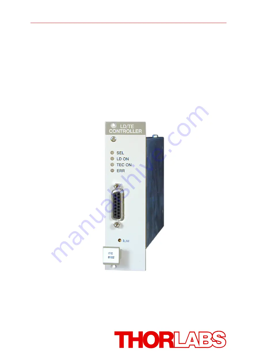
Page 18: ...____________________________________________________________________________________________________ 2010 Thorlabs 1 4 Operating elements at the front of the module Connector for the TEC element Connector for the laser diode Potentiometer for ILIM Connector for both laser diode and TEC Figure 1 The ITC8xxx and ITC8xxxDS15 front panel ...
Page 19: ...e used hardware limit ILIM software limit IMAX and software limit ITE LIM 1 5 1 Hardware limit ILIM The hardware limit ILIM for the laser diode current is set with the potentiometer marked ILIM at the front panel of the ITC8 Refer to chapter 1 4 Operating elements at the front of the module on page 12 The value is displayed continually in the channel menu of the module so you can watch it during a...
Page 20: ...d changed in the channel menu of the module or via the IEEE 488 interface Software limit IMAX CH2 ULD 0 0000 V CC off Imax 200 0mA TH off ILIM 188 22mA CHANGE CH2 ITE 0 0000 A CC off UTE 0 0000 V TH off ITE LIM 0 800 A CHANGE Software limit ITE LIM The software limits IMAX and ITE LIM have exactly the same protective function as the hardware limit Refer to chapter 2 2 Functions in the channel menu...
Page 21: ... laser diode and the TEC element are always sourced relative to ground by the combined module This is of considerable advantage regarding the safety of devices and stability of currents The monitor diode input is a trans impedance amplifier input with input impedance 0Ω The monitor diode input can be operated without or with bias voltage 0 V 10 V The polarity for the monitor diode must be set acco...
Page 22: ...aser diode 7 laser diode cathode with polarity AG 8 laser diode anode with polarity CG 3 laser diode ground Monitor diode 4 monitor diode input 2 monitor diode ground Measurement input for laser diode voltage 9 laser diode anode 6 laser diode cathode We recommend to use separate lines drilled in pairs twisted pair in a common shield for laser diode current monitor diode current and laser voltage m...
Page 23: ...ose as possible to the laser diode to avoid measurement errors The ground conductor of the monitor diode pin 2 may be connected to the ground conductor of the laser diode pin 3 If this is necessary e g with laser diodes with integrated monitor diode and shared ground connector the ground conductors should be connected as close as possible to the laser diode to avoid measurement errors when measuri...
Page 24: ...t a low resistance R 430 Ω must be maintained between the two pins With the contacts open or resistance too high the current module cannot be switched on Should the interlock contact open during operation the output will be switched off immediately Status display It is also possible to use a LED with a 0 5 kΩ resistor in parallel between the two pins The LED will light up if the current output is ...
Page 25: ...assignment of the TEC connector female Pin Function TEC element 5 6 TEC element 13 14 15 TEC element ground Status LED 1 Status LED anode 8 Status LED cathode ground Temperature sensor 3 Thermistor ground 4 Thermistor 10 AD590 PT100 for ITC8xxxPT 11 AD590 PT100 for ITC8xxxPT Connect the TEC element and the temperature sensor with shielded cables to the TEC connector The shielding of the cable must...
Page 26: ..._______________________________________________________________________ 2010 Thorlabs 1 6 5 Connecting a thermistor The thermistor is connected between pin 3 and pin 4 Figure 5 Connecting a thermistor 1 6 6 Connecting an AD590 The IC temperature sensor AD590 is connected between pin 10 and pin 11 Figure 6 Connecting an AD590 AD 590 10 11 ...
Page 27: ..._________________________________________________ 2010 Thorlabs 1 6 7 Connecting an LM335 The IC temperature sensor LM335 is connected between pin 10 pin 11 and pin 8 Figure 7 Connecting an LM335 1 6 8 Connecting the TEC element Connect the TEC element to pins 5 and 6 and the pins 13 14 and 15 for 13 15 14 5 6 Figure 8 Connecting a TEC element LM 335 10 11 8 ...
Page 28: ...heck of the TEC element Observe TACT or RACT and switch on the module by pressing the key ON OFF If TACT or RACT runs away from TSET or RSET the TEC element is reverse poled Change polarity and repeat the procedure If TACT or RACT is oscillating around the value TSET or RSET the TEC element is connected correctly but the P I and D share values of the control loop are still incorrect If TACT or RAC...
Page 29: ...C8xxxDS15 D SUB I O jack female PIN Function TEC element 8 TEC ground 7 TEC Temperature sensor 6 AD 590 13 AD 590 14 Thermistor ground 15 Thermistor Laser diode 11 Laser diode anode polarity CG 3 Laser diode ground 10 Laser diode cathode polarity AG Monitor diode 2 Monitor diode ground 4 Monitor diode anode or cathode Bias Measurement input for laser diode voltage 9 ULD cathode 12 ULD anode Interl...
Page 30: ...rmistor AD590 LM335 A heat source or sink air or water cooling element A heat conductor connecting the component to the source sink copper aluminum A propulsion to lead the thermal flow TEC element laser sensor copper bloc TEC element heat sink Figure 10 Principle set up of laser temperature control Influences on the real temperature control loop To 1 Offset and gain errors of the sensor allow onl...
Page 31: ...le to the laser temperature it also has a non negligible heat capacity Possible optimization careful adjustment of PID parameters 1 7 2 PID adjustment Temperature control loops are comparatively slow with control oscillations in the Hertz range The PID adjustment will optimize the dynamic behavior With the TED8xxx the three parameters P I and D can be set independently from 0 1 to 100 Example of a...
Page 32: ...e actual temperature Increase the D share gradually Higher values will decrease the amplitude of the overshoots The D share is set correctly when the actual temperature remains stable near the set temperature after a minimum of overshoots I share Turn on the I share again Again change repeatedly between set temperatures of 18 C and 22 C Increase the I share gradually Higher values will accelerate ...
Page 33: ...ues 2 1 Functions in the main menu 2 1 1 Display The main menu shows the channel number and the two most important operating parameters of the ITC8xxx module channel no Cursor first second parameter CH1 122 3mA 30 0 C CH2 CH3 CHANGE In constant current mode the first parameter is the laser current ILD in mA or A and the second value is the temperature T in C In constant power mode the first parame...
Page 34: ...or with the softkeys and to the desired channel number CH2 Pressing will lead to the channel menu Refer to chapter 2 2 Functions in the channel menu starting on page 29 2 1 3 Setting the main parameter To set the main parameter move the cursor to the desired channel number here CH1 CH1 122 3mA 30 0 C CH2 CH3 TUNE Press the softkey TUNE to turn the cursor to the right CH1 122 3mA 30 0 C CH2 CH3 TUN...
Page 35: ... procedure NOTE If the TEC current is switched ON the actual temperature is displayed In this case the set temperature can still be changed but is not displayed 2 2 Functions in the channel menu The channel menu is reached from the main menu by pressing the key Hit again or to return to the main menu 2 2 1 Display In the channel menu all parameters of the selected module are shown channel no curso...
Page 36: ...roll function All parameters are sorted in a virtual list which can be run through with the cursor ILD 44 000mA PLD 0 70000mW TA 22 60 C TS 15 00 C ULD 1 86V Imax 50 00mA ILIM 55 6mA IPD 0 0500mA C 1 00000A W UBIA 2 000 V MODE Iconst LDPOL AG PDPOL CG TWIN 0 461 C TWIN off TEC off ITE 0 000 A UTE 0 48 V ITE LIM 1 000 A Psh 5 0 Ish 15 0 Dsh 10 0 Ishare ON Thermistor Rs 10 000 kΩ RA 40 959 kΩ RWIN 0...
Page 37: ...nsor is AD 590 TH on off sensor is thermistor Open TEC output switched on but too high impedance ILK interlock open OVL laser diode output open LIM laser on but current has reached the limit value WIN TEC temperature out of activated temperature window Vcc fail OTP over temperature SENS wrong or no sensor connected 2 2 2 Changing parameters To set or change a numerical set parameter in the channel...
Page 38: ...he laser voltage or may not be changed during the laser switched on In this cases access is denied indicated by a long beep 2 2 3 Selecting the polarity of the laser and the monitor diode To change the polarity of the laser diode select the parameter LDPOL and select the desired polarity with CHANGE and toggle with AG CG To change the polarity of the monitor diode select the parameter PDPOL and se...
Page 39: ...Refer to chapter 2 2 2 Changing parameters on page 31 2 2 6 Selecting constant current or constant power mode The current modules ITC8xxx offer two operating modes for the laser diode In constant current mode the laser diode current is kept constant If the temperature of the laser changes the optical power will change too since the efficiency of the laser will change If the set up uses a monitor d...
Page 40: ...ype and press 2 2 8 Calibrating a thermistor 2 2 8 1 Select the calculation method If the relation between temperature and resistance for a given thermistor is known the PRO8 system is able to display temperature directly in C instead of resistance in Ω Therefore a calibration of the sensor in C is necessary Two well known methods to calculate the resistance from temperature are implemented The ex...
Page 41: ...ture typ 298 15 K 25 C Bval Energy constant temperatures in Kelvin For R0 T0 and Bval please refer to the data sheet of the thermistor To change the three parameters select them one by one and change them to the desired value Refer to the data sheet of the thermistor To change the three parameters R0 B T0 select them one by one and change them to the desired value Pressing will make every setting ...
Page 42: ...ivating the temperature protection To activate or deactivate the temperature protection select the parameter Twin ON resp Twin OFF in the channel menu of the module 2 2 11 Setting the P I and D share of the control loop The temperature control behavior of the ITC8xxx can be adapted optimally to the individual laser set up by optimizing the parameters P I and D share of the control loop They can be...
Page 43: ... laser diode with a screwdriver The corresponding potentiometer is marked ILIM and is located at the front panel of the combined module Refer to chapter 1 5 1 Hardware limit ILIM starting on page 13 Switching on off the laser diode current ILD in the channel menu Pressing the key will switch the module on or off not regarding the menu you are in as long as the module is selected LED SEL lights The...
Page 44: ..._________________________ 2010 Thorlabs Switching on off the TEC current in the channel menu To switch on the TEC current select TEC OFF in the channel menu and toggle to TEC ON and vice versa The LED ON at the module will light up when switched on and the status display changes from TH off to TH on In the main menu the set value TS changes to the actual value TA CH1 122 3mA 30 20 C ...
Page 45: ...Possible error messages of an ITC8xxx module 1 in case of interrupted operation Vcc fail Internal supply voltage failure Please contact Thorlabs OTP Over Temperature Protection Module has been switched off due to overheating Operation is possible again after cooling down ctrl Temp TACT exceeded TWIN the laser was switched off OPEN Laser was switched off due to interrupted connection or voltage acr...
Page 46: ...rotection Module is overheated and cannot be switched on Vcc fail Internal supply voltage failure Please contact Thorlabs INTERLOCK Laser cannot be switched on due to interlock circuit interruption Twin Temperature is out of window when window is activated 4 when trying to switch on TEC controller NO SENSOR No sensor connected or wrong sensor found OTP Over Temperature Protection Module is overhea...
Page 47: ...log values are read and written in SI units i e A not mA W not mW etc Letters may be written in small or capital letters Attention Before programming a current module first set the limit value of the laser diode current ILIM hardware limit for the applied laser diode with a screwdriver The corresponding potentiometer is marked ILIM and is situated at the front of the ITC8xxx module The value ILIM ...
Page 48: ...ring Examples A or ABGRS or A125TG or A1 23456A Refer to IEEE488 2 8 7 1 Numeric response data Type 1 NR1 Is a numerical value with sign in integer notation Examples 1 or 1 or 22 or 14356789432 Refer to IEEE488 2 8 7 2 Numeric response data Type 2 NR2 Is a numerical value with or without sign in floating point notation without exponent Examples 1 1 or 1 1 or 22 1 or 14356 789432 Refer to IEEE488 2...
Page 49: ...t for further programming Nr1 1 8 PRO8000 1 2 PRO800 SLOT Queries the selected slot SLOT NR1 LF 3 2 2 Calibrating a photo diode CALPD Programming CALPD SET NR3 Programs the sensitivity calibration factor η of the monitor diode A W Reading CALPD SET Reads the sensitivity η of the monitor diode CALPD SET NR3 LF CALPD MIN Reads the minimum allowed sensitivity η of this module CALPD MIN NR3 LF CALPD M...
Page 50: ...LTT SET NR3 LF CALTB MIN Reads the minimum Bval allowed CALTB MIN NR3 LF CALTR MIN Reads the allowed minimum R0 CALTR MIN NR3 LF CALTT MIN Reads the allowed minimum T0 CALTT MIN NR3 LF CALTB MAX Reads the allowed maximum Bval CALTB MAX NR3 LF CALTR MAX Reads the allowed maximum R0 CALTR MAX NR3 LF CALTT MAX Reads the allowed maximum T0 CALTT MAX NR3 LF Refer to chapter 2 2 8 2 Exponential method o...
Page 51: ... Steinhart Hart coefficient C1 CALTC1 SET NR3 LF CALTC2 SET Reads the Steinhart Hart coefficient C2 CALTC2 SET NR3 LF CALTC3 SET Reads the Steinhart Hart coefficient C3 CALTC3 SET NR3 LF CALTC1 MIN Reads the minimum C1 allowed CALTC1 MIN NR3 LF CALTC2 MIN Reads the minimum C2 allowed CALTC2 MIN NR3 LF CALTC3 MIN Reads the minimum C3 allowed CALTC3 MIN NR3 LF CALTC1 MAX Reads the maximum C1 allowed...
Page 52: ...eading ILD SET Reads the laser diode set current ILD SET NR3 LF ILD ACT Reads the actual laser diode current ILD ACT NR3 LF ILD MIN Reads the minimum laser diode current allowed ILD MIN NR3 LF ILD MAX Reads the maximum laser diode current allowed ILD MAX NR3 LF ILD MIN_W Reads the minimum laser diode current for Ild DAC 0000 ILD MIN_W NR3 LF ILD MAX_W Reads the maximum laser diode current for Ild ...
Page 53: ...ELCH IMD MEAS NR1 Programs the monitor diode current to be measurement value in the ELCH output string on position NR1 1 8 Reading IMD SET Reads the monitor diode set current IMD SET NR3 LF IMD ACT Reads the actual monitor diode current IMD ACT NR3 LF IMD MIN Reads minimum monitor diode set current allowed IMD MIN NR3 LF IMD MAX Reads maximum monitor diode set current allowed IMD MAX NR3 LF IMD MI...
Page 54: ... INTEG Programming INTEG ON Switches the I share on INTEG OFF Switches the I share off Reading INTEG Reads status of the I share INTEG ON LF INTEG OFF LF 3 2 8 Reading the TEC current ITE Programming ITE MEAS NR1 Programs the TEC current as measurement value on position NR1 in the output string for ELCH NR1 1 8 Reading ITE ACT Reads the actual TEC or heater current ITE ACT NR3 LF ITE MIN_R Reads t...
Page 55: ...s anode on ground LDPOL CG Selects cathode on ground Reading LDPOL Reads the laser diode polarity LDPOL AG LF LDPOL CG LF 3 2 11 Programming the laser diode software limit LIMC Programming LIMC SET NR3 Programs the laser diode current limit Reading LIMC SET Reads the laser diode current limit LIMC SET NR3 LF LIMC MIN Reads the minimum possible laser diode current limit LIMC MIN NR3 LF LIMC MAX Rea...
Page 56: ...3 3 2 13 Programming the TEC current software limit LIMT Programming LIMT SET NR3 Programs the TEC software current limit Reading LIMT SET Reads the TEC current software limit LIMT SET NR3 LF LIMT MIN Reads the minimum allowed TEC software current limit LIMT MIN NR3 LF LIMT MAX Reads the maximum allowed TEC software current limit LIMT MAX NR3 LF LIMT MIN_W Reads ITE LIM ADC 0000 LIMT MIN_W NR3 LF ...
Page 57: ...ogramming the optical power POPT Programming POPT SET NR3 Programs the optical power Reading POPT SET Reads the set optical power POPT SET NR3 LF POPT ACT Reads the actual optical power POPT ACT NR3 LF POPT MIN Reads the minimum allowed set optical power POPT MIN NR3 LF POPT MAX Reads the maximum allowed set optical power POPT MAX NR3 LF POPT MIN_W Reads the optical power for PLD DAC 0000 POPT MIN...
Page 58: ... string position NR1 1 8 Reading RESI SET Reads the set resistance of the sensor thermistor RESI SET NR3 LF RESI ACT Reads the actual resistance of the sensor RESI ACT NR3 LF RESI MIN Reads the minimum allowed set resistance of the sensor RESI MIN NR3 LF RESI MAX Reads the maximum allowed set resistance of the sensor RESI MAX NR3 LF RESI MIN_W Reads R DAC 0000 RESI MIN_W NR3 LF RESI MAX_W Reads R ...
Page 59: ...sistance window Reading RWIN SET Reads the set resistance window RWIN SET NR3 LF RWIN MIN Reads the minimum allowed set resistance window RWIN MIN NR3 LF RWIN MAX Reads the maximum allowed set resistance window RWIN MAX NR3 LF RWIN MIN_W Reads Rwin DAC 0000 RWIN MIN_W NR3 LF RWIN MAX_W Reads Rwin DAC FFFF RWIN MAX_W NR3 LF 3 2 19 Selecting the sensor SENS Programming SENS AD Sensor is AD590 family...
Page 60: ...EI SET NR3 LF SHARED SET Reads the D share SHARED SET NR3 LF SHAREP MIN Reads the minimum allowed P share SHAREP MIN NR3 LF SHAREI MIN Reads the minimum allowed I share SHAREI MIN NR3 LF SHARED MIN Reads the minimum allowed D share SHARED MIN NR3 LF SHAREP MAX Reads the maximum allowed P share SHAREP MAX NR3 LF SHAREI MAX Reads the maximum allowed I share SHAREI MAX NR3 LF SHARED MAX Reads the max...
Page 61: ... actual temperature TEMP ACT NR3 LF TEMP MIN Reads the minimum allowed set temperature TEMP MIN NR3 LF TEMP MAX Reads the maximum allowed set temperature TEMP MAX NR3 LF TEMP MIN_W Reads T DAC 0000 TEMP MIN_W NR3 LF TEMP MAX_W Reads T DAC FFFF TEMP MAX_W NR3 LF TEMP MIN_R Reads T ADC 0000 TEMP MIN_R NR3 LF TEMP MAX_R Reads T ADC FFFF TEMP MAX_R NR3 LF TEMP MEAS Reads string position 1 8 of tempera...
Page 62: ... Programming TWIN SET NR3 Programs the temperature window Reading TWIN SET Reads the set temperature window TWIN SET NR3 LF TWIN MIN Reads the minimum allowed set temperature window TWIN MIN NR3 LF TWIN MAX Reads the maximum allowed set temperature window TWIN MAX NR3 LF TWIN MIN_W Reads Twin DAC 0000 TWIN MIN_W NR3 LF TWIN MAX_W Reads Twin DAC FFFF TWIN MAX_W NR3 LF 3 2 25 Read Type of module TYP...
Page 63: ...rograms the bias start voltage for ELCH VBIAS STOP NR3 Programs the bias stop voltage for ELCH Reading VBIAS SET Reads the bias voltage VBIAS SET NR3 LF VBIAS MIN Reads the minimum allowed bias voltage VBIAS MIN NR3 LF VBIAS MAX Reads the maximum allowed bias voltage VBIAS MAX NR3 LF VBIAS MIN_W Reads UBIAS DAC 0000 VBIAS MIN_W NR3 LF VBIAS MAX_W Reads UBIAS DAC FFFF VBIAS MAX_W NR3 LF VBIAS START...
Page 64: ...ser voltage VLD ACT NR3 LF VLD MIN_R Reads ULD ADC 0000 VLD MIN_R NR3 LF VLD MAX_R Reads ULD ADC FFFF VLD MAX_R NR3 LF VLD MEAS Reads the position of VLD the ELCH output string 1 8 0 if not selected VLD MEAS NR1 LF 3 2 28 Reading the TEC voltage VTE Reading VTE MEAS NR1 Select TEC voltage to be measurement value for ELCH on string position NR1 1 8 Reading VTE ACT Reads the actual TEC voltage VTE A...
Page 65: ... and cannot be switched on 1304 Internal power failure Possible reason Severe hardware error Contact Thorlabs 1305 No calibrating of sensor during TEC on Reason The sensor cannot be calibrated when TEC controller is switched on 1306 No calibrating of PD during laser on in constant power mode Reason The monitor diode cannot be calibrated for constant power mode when laser output is switched on 1307...
Page 66: ...on Attempt to switch on the TEC controller while no sensor is connected or wrong sensor is selected 1313 Wrong command for this sensor Reason The used command is not allowed for the selected sensor e g attempt to set a thermistor resistance value while the selected and recognized sensor is an AD590 1314 No sensor change during TEC on allowed Reason The sensor type cannot be changed when the TEC ou...
Page 67: ...C8xxxx modules provide three 16 bit registers DEC DEE and EDE see Figure 11 together with four 8 bit registers ESR STB ESE and SRE see Figure 12 of the mainframe to program various service request functions and status reporting Please refer to the IEEE488 2 1992 standard chapter 11 Figure 11 The ITC8xxx device error registers DEC DEE and EDE STAT DECn n Slot number Open circuit TEC No or wrong sen...
Page 68: ..._____________________________ ______________________________________________________________________________________________________ 2010 Thorlabs Figure 12 The PRO8000 4 PRO800 register ESR ESE STB and SRE Output buffer ERROR Queue or serial poll Service Request Generation ...
Page 69: ...ror occurred Device dependent error A device dependent error occurred Query error A query error occurred Request control Not used Operation complete Can be set with OPC The ESR can be read directly with the command ESR This read command clears the ESR The content of the ESR cannot be set The bits are active high 3 4 2 Standard event status enable register ESE The bits of the ESE are used to select...
Page 70: ...mmand has finished and all bits of the STB have been set The STB can be read directly with the command STB The content of the STB cannot be set The bits are active high All bits except bit 6 of the STB can be used to assert a service request SRQ see 3 4 5 Alternatively the SRQ can be recognized using the command STB see 3 4 6 or by serial poll see 3 4 7 3 4 4 Service request enable register SRE Th...
Page 71: ...ance is 430 Ω 3 Current limit The current limit is reached and the protection circuit is active now Noise and drift specs are not valid any more 4 Temperature out of window TEC temperature is out of specified window 5 Open circuit TEC TEC circuit is open 6 No or wrong sensor Temperature sensor not connected or wrong type 8 Power supply error Internal power supply error The DEC can be read but not ...
Page 72: ...rly to the mains Connect the PRO8000 4 PRO800 to the power line take care of the right voltage setting of your mainframe Mainframe PRO8000 4 PRO800 turned on Turn on your PRO8000 4 PRO800 with the key mains switch Control the fuse at the rear panel of the PRO8000 4 PRO800 mainframe If blown up replace the fuse by the correct type refer to your PRO8000 4 PRO800 mainframe operating manual to select ...
Page 73: ...ust the hardware limit ILIM by means of the potentiometer on the ITC8xxx front panel and the software limit IMAX in the channel menu to ap propriate values Is the output power set to 0 Adjust the output power in the channel menu or with the command POPT SET NR3 Is the laser diode installed properly Control the connection cable Is the laser diode poled correctly If not change the polarity with the ...
Page 74: ...Check the correct polarity see section 1 6 9 Polarity check of the TEC element page 22 Is the temperature sensor connected properly and are his parameters entered correctly Check the corresponding connections and polarities of the temperature sensor refer to chapters1 6 5 to 1 6 7 Check the software settings in the channel menu Select the corresponding temperature sensor Enter the right set values...
Page 75: ... etc which should arise have to be carried by the customer Thorlabs warrants the hard and software determined by Thorlabs for this unit to operate fault free provided that they are handled according to our requirements However Thorlabs does not warrant a faulty free and uninterrupted operation of the unit of the soft or firmware for special applications nor this instruction manual to be error free...
Page 76: ...or institute within the EC currently owned by a company or institute within the EC still complete not disassembled and not contaminated As the WEEE directive applies to self contained operational electrical and electronic products this end of life take back service does not refer to other Thorlabs products such as pure OEM products that means assemblies to be built into a unit by the user e g OEM ...
Page 77: ...cal background It is well known that WEEE pollutes the environment by releasing toxic products during decomposition The aim of the European RoHS directive is to reduce the content of toxic substances in electronic products in the future The intent of the WEEE directive is to enforce the recycling of WEEE A controlled recycling of end of life products will thereby avoid negative impacts on the envi...
Page 78: ...e Clear DEC Device Error Condition Register DEE Device Error Event Register DES Device Error Status EAV Error AVailable EDE Enable Device Error Event Register ELCH ELectrical Characterization EOI End Of Information ESE Standard Event Status Enable register ESR Event Status Register FIN Command FINished GET Group Execute Trigger GTL Go To Local GPIB General Purpose Interface Bus IEEE Institute for ...
Page 79: ..._________________________________________________________________ 2010 Thorlabs PC Personal Computer P Share Proportional share RQS ReQuest Service Message SDC Selected Device Clear SEL SELect SRE Service Request Enable Register SRQ Service ReQuest STB STatus Byte Register SW Soft Ware TEC ThermoElectric Cooler Peltier Element TRG TRiGger ...
Page 80: ...nnector female 16 Figure 3 Pin assignments of laser and photodiode 17 Figure 4 Pin assignment of the TEC connector female 19 Figure 5 Connecting a thermistor 20 Figure 6 Connecting an AD590 20 Figure 7 Connecting an LM335 21 Figure 8 Connecting a TEC element 21 Figure 9 ITC8xxxDS15 D SUB I O jack female 23 Figure 10 Principle set up of laser temperature control 24 Figure 11 The ITC8xxx device erro...
Page 81: ...nt Burst Immunity Performance criterion C IEC 61000 4 5 Power Line Surge Immunity Performance criterion C IEC 61000 4 6 Conducted RF Immunity Performance criterion B IEC 61000 4 11 Voltage Dips and Interruptions Immunity Performance criterion C EN 61000 3 2 AC Power Line Harmonic Emissions Complies with the Radiocommunications Act and demonstrated per EMC Emission standard1 2 3 AS NZS 2064 Industr...
Page 82: ...amage or damages suffered by third parties resulting from the purchase of this product In no event shall any liability exceed the purchase price of the product Please note that the content of this User Manual is neither part of any previous or existing agreement promise representation or legal relationship nor an alteration or amendment thereof All obligations of Thorlabs GmbH result from the resp...
Page 83: ...eckler Str 6 D 85221 Dachau Munich Germany Sales and Support Phone 49 0 81 31 5956 0 Fax 49 0 81 31 5956 99 Email europe thorlabs com Web www thorlabs de USA Thorlabs Inc 435 Route 206 North Newton NJ 07860 USA Sales and Support Phone 1 973 579 7227 Fax 1 973 300 3600 Email sales thorlabs com techsupport thorlabs com Web www thorlabs com Japan Thorlabs Japan Inc Higashi Ikebukuro Q Building 1st fl...
Page 84: ...horlabs China Oasis Middlering Centre 3 Building 712 Room 915 Zhen Bei Road Shanghai China Sales and Support Phone 86 0 21 32513486 Fax 86 0 21 32513482 Email chinasales thorlabs com Web www thorlabs com Our company is also represented by several distributors and sales offices throughout the world Please call our hotline send an Email to ask for your nearest distributor or just visit our homepage ...