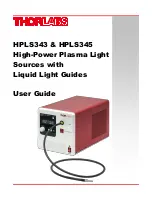
HPLS343 & HPLS345 High-Power Plasma Light Sources with Liquid Light Guides
User Guide
Page 1: ...HPLS343 HPLS345 High Power Plasma Light Sources with Liquid Light Guides User Guide...
Page 2: ...9 5 1 Starting the Light Source 9 5 2 LCD Screen 10 5 3 Shutter Operation 10 5 4 Intensity Tuning 10 5 5 External Control 10 5 5 1 External Shutter Operation 11 5 5 2 ANALOG IN and TRIGGER IN 11 5 5 3...
Page 3: ...INT Device Power Intensity 25 8 3 7 SHT n SHT Shutter 25 8 3 8 LAT Bulb Module Temperature 26 8 3 9 LLG Light Guide Temperature 26 8 3 10 MOD n MOD Device Control Mode 26 8 3 11 LAD n LAD Operation M...
Page 4: ...ice Symbol Description Direct Current Alternating Current Both Direct and Alternating Current Earth Ground Terminal Protective Conductor Terminal Frame or Chassis Terminal Equipotentiality On Supply O...
Page 5: ...ve environments CAUTION Do not operate in wet damp conditions WARNING Do NOT look directly at the light source beam during operation Do NOT place hand or body part in the light beam as this may result...
Page 6: ...ma excited in the bulb produces light with a complete color spectrum As the bulb module does not include electrodes it is efficient and has a long lifetime The LEP bulb module consists of two fundamen...
Page 7: ...tips on both ends The LLG offers a large core size and high NA and its transmission window includes the entire visible spectrum Thus an LLG are is a powerful tool to deliver the intense light output f...
Page 8: ...Elements Figure 3 Front and Back Panel of the HPLS343 HPLS345 Light Sources F1 External Control Button with LED F2 LCD Screen F3 Shutter Control Button F4 Light Intensity Adjustment Knob F5 Liquid Lig...
Page 9: ...own in Figure 4 by using Thorlabs table clamp CL6 or CL8 together with one of Thorlabs baseplates one can securely mount the plasma light source onto the surface of an optical table or breadboard with...
Page 10: ...LLGs featuring the yellow marking ring with these light sources though all of Thorlabs standard liquid light guides are compatible taking core diameter into consideration When using an LLG that does...
Page 11: ...X Microscopes Leica DMI Microscopes Zeiss Axioskop Microscopes Nikon Eclipse Ti Microscopes Item Photo Item LLG3A1 A LLG5A1 A LLG3A2 A LLG5A2 A LLG3A4 A LLG5A4 A LLG3A5 A LLG5A5 A LLG Core Diameter 3...
Page 12: ...Starting the Light Source Make sure both the power cable and the liquid light guide are securely connected then press power switch to turn on the light source After the light source is turned on an i...
Page 13: ...ay cause permanent damage to the eye Do NOT place hand or body part on the tip of the light guide during operation as this may result in burns NEVER place objects on the tip of the light guide during...
Page 14: ...ort to cause a change in the intensity a trigger signal must be sent to the TRIGGER IN port This female BNC accept 5 V CMOS When the falling edge of the pulse sent to the TRIGGER IN port is detected t...
Page 15: ...rding to the ANALOG IN signal Meanwhile the state of TRIGGER OUT will change from HIGH to LOW When the tuning is finished the ANALOG OUT will output a voltage according to the new intensity and the TR...
Page 16: ...e which stabilizes the light source at 80 of its maximum light intensity in open loop mode In closed loop mode the light source utilizes a photodetector to monitor the bulb s optical intensity level A...
Page 17: ...clude the effects of travelling through the LLG The LLG acts to homogenize the light it transmits and also gradually become less transmissive when exposed to UV light Closed loop mode compensates for...
Page 18: ...oes not clear within an hour it will be upgraded to an error To clear the error close the shutter and remove the liquid light guide from the light source Allow the LLG to cool down for at least 30 min...
Page 19: ...ature of the bulb module may reach over 75 C during operation Always wait at least 10 minutes after turning off the light source for cool down before performing a bulb module replacement When performi...
Page 20: ...back panel with the included 2 mm hex key Then remove the red cover by sliding it backwards Figure 16 Remove the six screws on the back panel Figure 17 Slide the red cover backwards to take it out Th...
Page 21: ...e the included 3 mm hex key to remove the two cap crews close to the back panel Figure 19 Remove Two Cap Screws on the Back There are two cables connected to the bulb module from beneath as shown in F...
Page 22: ...pulling the connector carefully downward Figure 21 Remove the Smaller Cable First Hold the bulb module firmly and slide it backwards until it completely disconnects from the lens holder in front of i...
Page 23: ...ide the light source is firmly inserted in the front opening of the bulb module 4 Connect the small cable beneath the bulb module as shown in Figure 21 5 Thread in the two cap screws and tighten with...
Page 24: ...y adjustment shutter control and toggling between manual and external control modes In addition the GUI provides users with direct temperatures reading of both the bulb module lamp temperature and the...
Page 25: ...sent The basic structure of the interface is a keyword followed by either an equals sign or a question mark The or character determines if the string is a command or a query All strings commands and q...
Page 26: ...hutter open closed 1 closed 2 open Get Shutter State SHT Return the shutter state 1 closed 2 open Get Bulb Module Temperature LAT Return bulb Module temperature Get Light Guide Temperature LLG Return...
Page 27: ...2 remote MOD n Set control mode 1 local 2 remote LAD Get Lamp mode 1 close loop 2 open loop 3 eco LAD n Set lamp mode 1 close loop 2 open loop 3 eco LON Get lamp on off status 0 off 1 on LON n Set la...
Page 28: ...to 100 0 in INT Queries current device power intensity Return INT n Where n is current device power intensity percentage Please notice that the largest delay of output power intensity reaching to the...
Page 29: ...erature Return LLG n Where n is the value of light guide temperature in C 8 3 10 MOD n MOD Device Control Mode The MOD command is used to set or query the device control mode There are two available m...
Page 30: ...ode If n is out of current list range the controller returns CMD_ARG_RANGE_ERR 8 3 12 LON n LON Bulb Module ON OFF The LON command is used to set or query the bulb module on off status LON n Turn the...
Page 31: ...le temperature too high 0000 0010 bulb module fail 0000 0100 LLG temperature too high More than one error indication can be supported NOTE The device should be restarted for normal operation after it...
Page 32: ...t Intensity non linearity 2 Bulb Module Lifetime5 6000 h Typ Intensity Switch Time 3 s 10 to 90 Intensity Shutter Switch Time 5 ms Maximum Shutter Repetition Rate 1 Hz Long Term 10 Hz Burst Power Supp...
Page 33: ...Plasma Light Sources with Liquid Light Guide Chapter 10 Mechanical Drawing Page 30 CTN009142 D02 Chapter 10 Mechanical Drawing Figure 24 Mechanical Drawing...
Page 34: ...Plasma Light Sources with Liquid Light Guide Chapter 11 Certifications and Compliances Rev F June 12 2019 Page 31 Chapter 11 Certifications and Compliances...
Page 35: ...Plasma Light Sources with Liquid Light Guide Chapter 11 Certifications and Compliances Page 32 CTN009142 D02...
Page 36: ...er to other Thorlabs products such as Pure OEM products that means assemblies to be built into a unit by the user e g OEM laser driver cards Components Mechanics and optics Left over parts of units di...
Page 37: ...nformation USA Canada and South America Thorlabs Inc sales thorlabs com techsupport thorlabs com Europe Thorlabs GmbH europe thorlabs com France Thorlabs SAS sales fr thorlabs com Japan Thorlabs Japan...
Page 38: ...www thorlabs com...