background image

EXULUS

®

 Spatial Light Modulators


Chapter 4: Setup and Software Operation


Rev F, December 7, 2020 

Page 35 


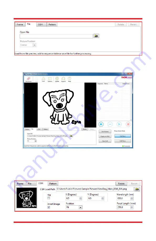
The uploaded image is converted automatically to 8-bit gray scale. A scaling and/or 
cropping is applied for images with resolution that is different  than the panel and 
is selected in the Picture Position list. 


Figure 47  Uploaded PNG File in Fit Position 

CGH Mode 

Computer  Generated  Holography  (CGH)  is  a  widely  used  method  of  digitally 
generating holographic interference patterns. In this mode, a fast CGH algorithm 
is applied to generate such patterns. 


Figure 48  CGH Mode Settings 

Summary of Contents for EXULUS-HD2

Page 1: ...EXULUS HD2 EXULUS HD2HP EXULUS HD3 EXULUS HD3HP EXULUS HD4 Spatial Light Modulators User Guide ...

Page 2: ... 4 Operating Elements 9 3 4 1 Overview 9 3 4 2 Horizontal and Vertical Fine Adjusters Standard SLMs 11 3 4 3 SLM Head High Power SLMs 11 3 4 4 Trigger Output Connector SMA 11 3 4 5 Holes for 30 mm Cage System Standard SLMs 12 3 4 6 Post Mounting Holes 12 3 4 7 Removable Dust Cover Standard SLMs 13 Chapter 4 Setup and Software Operation 14 4 1 Installing the SLM 14 4 1 1 Mounting Method Conversion ...

Page 3: ...3 Operation Mode 33 4 5 4 Display Mode 34 4 5 5 Sequence Setting 39 4 5 6 Status Bar 40 Chapter 5 Troubleshooting 41 Chapter 6 Specifications 42 Chapter 7 Mechanical Drawings 44 Chapter 8 CE FCC Certification 47 Chapter 9 Warranty 51 Chapter 10 Regulatory 52 Chapter 11 Thorlabs Worldwide Contacts 53 ...

Page 4: ...ce Symbol Description Direct Current Alternating Current Both Direct and Alternating Current Earth Ground Terminal Protective Conductor Terminal Frame or Chassis Terminal Equipotentiality On Supply Off Supply In Position of a Bi Stable Push Control Out Position of a Bi Stable Push Control Caution Risk of Electric Shock Caution Hot Surface Caution Risk of Danger Warning Laser Radiation Caution ESD ...

Page 5: ... be performed by trained service personnel SHOCK WARNING High voltage inside To avoid electrical shock before powering up make sure that the ground pin of the power cord is correctly connected to the ground connector in the power socket Improper grounding can cause electric shock resulting in severe injury or even death Do not operate without the cover installed WARNING This unit must not be opera...

Page 6: ...dirt and air borne pollutants including cigarette smoke The system is not designed for outdoor use Protect the equipment from rain snow and humidity Do not expose to mechanical and thermal extremes Protect the equipment from rapid variations in temperature Handle all connectors with care Do not use unnecessary force as this may damage the connectors Handle the mainframe with care Mishandling may c...

Page 7: ...es to achieve the listed specifications this system should only be used with accessories provided by Thorlabs Any modification or servicing by unqualified personnel renders the warranty null and void leaving Thorlabs free of liability Custom version with panel and controller in separate units available please contact Tech Support for questions on customization ...

Page 8: ...echnology is a reflective retarder panel utilizing a liquid crystal layer sandwiched between a top transparent and conductive ITO layer and the reflective electrode layer on the bottom On the bottom layer pixels are arranged as individual addressable aluminum electrodes Together with the ITO layer on top an electric field is built by applying a voltage between the two layers The liquid crystal mod...

Page 9: ... Power SLMs Power Supply Item DS12 USB Cable HDMI Cable DP to HDMI Cable USB Drive with Software and Manual 2 mm Balldriver Ø2 Dust Proof Tape Tubing Clip 2 5 mm Stereo Cable for Thermistor Connection to Liquid Cooling System Item LK220 CPC Valved Quick Connection Fittings for 4 3 mm 0 17 Inner Diameter Hose CPC Valved Quick Connection Fittings for 6 0 mm 0 24 Inner Diameter Hose Figure 2 Standard...

Page 10: ...7 2020 Page 7 Figure 3 High Power SLM Main Unit with Adapter Board and SLM Head Pre mounted Figure 4 Power Supply Item DS12 Figure 5 USB Cable Figure 6 HDMI Cable Figure 7 DP HDMI Cable Figure 8 USB Drive with Software and Manual Figure 9 Hex Key Thumbscrew Item HKTS 5 64 ...

Page 11: ...0 mm 0 24 Inner Diameter Hose 2 pcs Figure 11 CPC Valved Quick Connection Fittings for 4 3 mm 0 17 Inner Diameter Hose 2 pcs Figure 12 2 5 mm Stereo Cable for Thermistor Connection with Liquid Cooling System Item LK220 Figure 13 2 mm Balldriver Item BD 2M Figure 14 Tubing Clip 4 pcs Figure 15 Ø2 Protective Tape for SLM Head 4 pcs ...

Page 12: ...ements 3 4 1 Overview Figure 16 Front View of Standard SLMs Callout Description 1 Horizontal Vertical Fine Adjusters 2 Power Input 3 HDMI Connector 4 Mini B USB 2 0 Connector 5 Trigger Output Connector SMA 6 Power Switch 7 30 mm Cage System Mounting Holes 4 40 Tap 4 Places 8 SLM Panel 1 2 3 4 5 6 7 8 ...

Page 13: ... Front View of High Power SLMs Callout Description 1 CPC Valved Quick Connection Fittings for 4 3 mm 0 17 Inner Diameter Hose 2 Power Input 3 HDMI Connector 4 Mini B USB 2 0 Connector 5 Trigger Output Connector SMA 6 Power Switch 7 Adapter Board 8 SLM Panel 9 SLM Head 1 2 3 4 5 6 7 8 9 9 ...

Page 14: ... connected to a 2 5 mm stereo jack see below Figure 18 Pin Diagram for Connecting to the Thermistor The SLM head is compatible with 30 mm cage system as well as the Polaris 1 mirror mount Item POLARIS K1 for additional panel tip tilt adjustments Two valved coupling inserts for 1 4 diameter hose are pre installed for easy connection to Thorlabs cooling system Item LK220 which is the recommended coo...

Page 15: ...ge system Figure 20 SLM with Attached 30 mm Cage System 3 4 6 Post Mounting Holes The mounting holes shown below in Figure 21 and Figure 22 are designed for Thorlabs optical posts Note that these are universal tapped holes which accept both 8 32 and M4 threaded screws Therefore either imperial or metric posts are compatible e g Item TR2 or TR50 M Figure 21 Two Mounting Holes on Bottom Standard SLM...

Page 16: ...r Standard SLMs Prior to shipping a magnetically coupled dust cover is installed on the front face of the Liquid Crystal panel Remove it before using your SLM While using the SLM the dust cover can be mounted on the back panel of the SLM main unit as illustrated in Figure 23 Figure 23 Two Mounting Holes on the Side and Cover Plate Storage on the Back Standard SLMs ...

Page 17: ...sulting in severe injury or even death Do not operate without the cover installed WARNING This unit must not be operated in explosive environments WARNING Transportation and delivery may cause the SLM to be warm or cool upon receipt Please wait for the whole device to reach room temperature before attempting to operate WARNING Do not operate in wet damp conditions Do not obstruct the air ventilati...

Page 18: ...er 7 2020 Page 15 Figure 24 Post Mounting the standard SLM with Thorlabs Ø1 2 Posts For High Power SLMs the following two mounting methods are available All in One Mode two tapped holes are available for mounting on the bottom Figure 25 Post Mounting the High Power SLM All in One Mode ...

Page 19: ...igure 26 Post Mounting the High Power SLM Separate Panel Mode Here the SLM head is compatible with the POLARIS K1 Ø1 Kinematic Mirror Mount for additional panel tip tilt adjustments Figure 27 SLM Head Mounted with the Polaris K1 Ø1 Kinematic Mirror Mount Note Always use the recommended Ø1 Polaris Kinematic Mirror Mount Item POLARIS K1 or other kinematic mirror mounts with flat front face plates to...

Page 20: ...eparate Panel Mode please always follow the steps as described below Step 1 Wear anti electrostatic band and talc free gloves before any operations DO NOT touch any electrodes on the PCBA that are integrated in the adaptor board Step 2 Disconnect the FPCs Open the lid of the Adapter Board by removing the two locking screws marked with red in Figure 28 with the included 2 mm balldriver Figure 28 Fr...

Page 21: ...er Board Figure 30 FPCs Disconnected with Adapter Board Connectors Step 3 Disassembly of Adapter Board and Panel Mount Remove the four screws of the adapter board see Figure 30 and loosen the four screws of SLM head see Figure 31 using a 2 mm balldriver to remove each part from the main unit see Figure 32 Board Side Panel Side ...

Page 22: ...e SLM head properly as the first step Use standard posts 8 32 M4 Taps or a Polaris K1 Ø1 Kinematic Mirror Mount for mounting then adjust the height of the head to make sure that the incident beam illuminates the center of the panel s active area Once the SLM head is fixed adjust the height of the adapter board and main unit to align the FPC of both the board and panel sides to the height of the co...

Page 23: ...and Panel Sides Then make sure that the FPC has been inserted correctly and fully into the two connectors see examples in Figure 34 and Figure 35 before closing the FPC connector lid avoiding any tilts Failing to do so can cause the panel to be damaged after power on Figure 34 Incorrect FPC Position While Inserted to FPC Connector ...

Page 24: ...ge 21 Figure 35 Correct FPC Position While Inserted to FPC Connector Close the connector lid to secure the FPC connection between the main body and panel head Figure 36 Well Connected FPC Between Main Body and Panel Install the adapter board lid by locking the two screws to finish the reassembly ...

Page 25: ...nts To run the EXULUS SLM software you need to have a computer that meets the following hardware requirements Operating System Windows 7 64 bit or Windows 10 64 bit One Available High Speed USB 2 0 Port CPU Intel Core i3 or Above RAM 2 GB or More One available HDMI Port or DisplayPort 4 3 Installing the Software The EXULUS SLM software can be downloaded from the Thorlabs website or from the bundle...

Page 26: ...EXULUS Spatial Light Modulators Chapter 4 Setup and Software Operation Rev F December 7 2020 Page 23 Installation of Main UI The main UI is installed in your computer first Click the Next to continue ...

Page 27: ...atial Light Modulators Chapter 4 Setup and Software Operation Page 24 CTN013676 D02 Click I accept the License Agreement and Next to continue the installation Click Next to finish the installation of the main UI ...

Page 28: ...ember 7 2020 Page 25 Installation of CP210x USB to UART Bridge Driver The installer proceeds to install the CP210x USB to UART Bridge driver Wait for the installation to be started Click the Next to continue Click I accept the License Agreement and Next to continue the installation ...

Page 29: ... 4 4 Connect the SLM to the PC To operate your SLM with your computer follow the steps below Connect the included power supply to the mains power and the DC input on the SLM Connect the SLM to a High Speed USB 2 0 port of your computer Use only the cable that is bundled with the SLM or a cable qualified for High Speed USB 2 0 standard Connect the SLM to a HDMI or DP port of your computer Use the p...

Page 30: ...mmend waiting for 30 minutes after power on before operating For the High Power SLMs we recommend using a liquid chiller item LK220 to stabilize the panel temperature after powering on Wait for Windows to recognize the hardware The SLM connects to the computer as a USB Serial Port Connection can be verified in the Device Manager under the Ports list Wait for Windows to detect the SLM display Check...

Page 31: ...ftware is ready to connect 4 5 Software GUI The Software GUI provides complete control of SLM panel If a High Power SLM is used the temperature reading from the liquid chiller Item LK220 is also available It is divided into six functional areas Main Menu Sequence Setting Preview Window Operation Mode Display Mode Status Bar Figure 37 Main UI Window of EXULUS SLM Software Status Bar Display Mode Op...

Page 32: ...el of your SLM 00190031 represents its serial number and CH3XVBJZ is the serial number of Liquid Chiller LK220 If there is no EXULUS or Liquid Chiller device listed check that the power switch is switched to ON and the USB cable is properly connected to your computer Otherwise please check Chapter 5 for a solution Select your SLM and Liquid Chiller if available and click Connect All the features a...

Page 33: ...in computer screen is recognized as Screen ID 1 and the SLM panel as Screen ID 2 However in some cases especially for systems with multiple screens the SLM s Screen ID might be different Therefore it needs to be properly set in the SLM Setting Window Otherwise the SLM does not respond to all the operations by this application Figure 40 SLM Screen ID Setting o Screen Flip Flip the SLM panel in the ...

Page 34: ...est Pattern Sensor Setting only available when the LK220 chiller is connected o Sensor Mode Internal provides the temperature reading from the output coolant temperature External provides the temperature reading from the thermistor of High Power SLM head read out by the LK220 If the external mode is selected while no sensor is connected to the liquid chiller an error message as well as alarm will ...

Page 35: ...he thresholds for changing from black font to red respectively Figure 43 Sensor Setting of the Liquid Chiller About Displays the version information about the SLM software Please have these details available when contacting Thorlabs Technical Support Figure 44 Software Version Information Update Updates the software to the latest version if any updates are available Support For technical support t...

Page 36: ...the control setting of the preview image Figure 45 Operation Mode Area Save Picture Allows the user to save the current preview pattern as a PNG image format with resolution of 1920 x 1200 Display on SLM Uploads the current preview pattern to the SLM Clear SLM Clear the displayed pattern on the SLM panel and reset the SLM with a black background Phase Stroke Mode The Full Wave mode provides a tota...

Page 37: ...nction for rotating the image preview Frame Mode File Mode CGH Mode Pattern Mode Rotate Function Frame Mode By default the software initially starts with Frame Mode A uniform gray level from 0 to 255 can be set by the user and a related gray scale pattern is created and shown in the preview window Figure 46 Frame Mode File Mode The file mode allows the user to upload a custom pattern in common ima...

Page 38: ...pping is applied for images with resolution that is different than the panel and is selected in the Picture Position list Figure 47 Uploaded PNG File in Fit Position CGH Mode Computer Generated Holography CGH is a widely used method of digitally generating holographic interference patterns In this mode a fast CGH algorithm is applied to generate such patterns Figure 48 CGH Mode Settings ...

Page 39: ... position and the inversion of black and white can be user defined before generation The wavelength which is set at 633 nm as the default for EXULUS HD2 EXULUS HD2HP 1064 nm for EXULUS HD3 EXULUS HD3HP and 1550 nm for EXULUS HD4 should be set so that it matches the wavelength of the light source Figure 49 Generated CGH Pattern of Uploaded Image Pattern Mode The pattern mode consists of four common...

Page 40: ...raction mode contains three parameters wavelength diffraction angle and rotation angle It is used to tilt steer the incoming beam to a specific angle Figure 51 Generation of Diffraction Pattern The Vortex mode contains two parameters wavelength and pattern order m This pattern creates a helical output beam and contains a characteristic donut beam profile ...

Page 41: ...Page 38 CTN013676 D02 Figure 52 Generation of Vortex Pattern The Cubic Phase mode contains two parameters wavelength and alpha It is used to generate a non diffracted beam with self recovery characteristics commonly called an Airy beam Figure 53 Generation of Cubic Pattern ...

Page 42: ...ge in the Preview Window clockwise by 90 The image can be restored to default by clicking the Revert button Figure 54 Image Rotation in Preview Window 4 5 5 Sequence Setting The Sequence Setting table consists of a list of pre defined patterns and four control buttons Each pattern is regarded as a frame and is displayed sequentially Figure 55 Sequence Setting Area ...

Page 43: ...ce Add to Sequence Add the current preview pattern into the sequence table Remove from Sequence Remove the selected pattern from the sequence table Play the Sequence Run the sequence with defined interval While playing the sequence this button can be used to temporarily pause the sequence playing Stop the Sequence Stop and quit the sequence mode 4 5 6 Status Bar The status bar displays information...

Page 44: ...Change power cord Power supply is broken Contact Thorlabs Technical Support GUI does not start USB port is not connected Connect the USB cable USB cable is broken Change USB cable System does not output correct pattern HDMI port is not connected Connect the HDMI cable HDMI cable is broken Change HDMI cable SLM display is not shown as extended Set the SLM display as extended Refer to Section 4 4 In...

Page 45: ...ale Trigger Output High Voltage Level 5 V TTL Trigger Output Pulse Width 54 µs Dimension L x W x H 3 155 9 mm x 104 3 mm x 42 0 mm Weight 0 76 kg Storage Temperature 0 to 60 C Operating Temperature4 10 to 40 C PC Connection HDMI and USB 2 0 Bit Depth 8 Bit 0 255 Gray Level 1 Other angles of incidence will result in phase shifts that differ from the programmed pattern Angles of up to 10 are possibl...

Page 46: ...nel Resolution 1920 x 1200 WUXGA Panel Active Area 15 42 mm x 9 66 mm Pixel Pitch 8 µm Fill Factor 92 Reflective Coating Aluminum Average Reflectance 80 Typical Phase Retardance Range1 2π at 633 nm Full Wave 2π at 1064 nm Full Wave π at 633 nm Half Wave π at 1064 nm Half Wave Angle of Incidence2 0 Optic Axis 0 Reflected Wavefront Distortion λ 2 633 nm 0 4λ 633 nm Optical Power Handling3 200 W cm F...

Page 47: ...EXULUS Spatial Light Modulators Chapter 7 Mechanical Drawings Page 44 CTN013676 D02 Chapter 7 Mechanical Drawings Figure 56 EXULUS HD2 EXULUS HD3 and EXULUS HD4 Diagram ...

Page 48: ...EXULUS Spatial Light Modulators Chapter 7 Mechanical Drawings Rev F December 7 2020 Page 45 Figure 57 EXULUS HD2HP and EXULUS HD3HP All in One Configuration Diagram ...

Page 49: ...EXULUS Spatial Light Modulators Chapter 7 Mechanical Drawings Page 46 CTN013676 D02 Figure 58 EXULUS HD2HP and EXULUS HD3HP Panel Separate Configuration Diagram ...

Page 50: ...EXULUS Spatial Light Modulators Chapter 8 CE FCC Certification Rev F December 7 2020 Page 47 Chapter 8 CE FCC Certification ...

Page 51: ...EXULUS Spatial Light Modulators Chapter 8 CE FCC Certification Page 48 CTN013676 D02 ...

Page 52: ...EXULUS Spatial Light Modulators Chapter 8 CE FCC Certification Rev F December 7 2020 Page 49 ...

Page 53: ...EXULUS Spatial Light Modulators Chapter 8 CE FCC Certification Page 50 CTN013676 D02 ...

Page 54: ...horlabs warrants material and production of your EXULUS for a period of 24 months starting with the date of shipment All specific warranty and repair information can be found in the general terms and conditions located at https www thorlabs com Images PDF LG PO 001_Thorlabs_terms_and_ 20agreements pdf ...

Page 55: ...her Thorlabs products such as Pure OEM products that means assemblies to be built into a unit by the user e g OEM laser driver cards Components Mechanics and optics Left over parts of units disassembled by the user PCB s housings etc If you wish to return a Thorlabs unit for waste recovery please contact Thorlabs or your nearest dealer for further information Waste Treatment is Your Own Responsibi...

Page 56: ...formation USA Canada and South America Thorlabs Inc sales thorlabs com techsupport thorlabs com UK and Ireland Thorlabs Ltd sales uk thorlabs com techsupport uk thorlabs com Europe Thorlabs GmbH europe thorlabs com Scandinavia Thorlabs Sweden AB scandinavia thorlabs com France Thorlabs SAS sales fr thorlabs com Brazil Thorlabs Vendas de Fotônicos Ltda brasil thorlabs com Japan Thorlabs Japan Inc s...

Page 57: ...www thorlabs com ...

Reviews: