EDFA100S and EDFA100P Erbium Doped Fiber Amplifiers Operating Manual
Page 1: ...EDFA100S and EDFA100P Erbium Doped Fiber Amplifiers Operating Manual ...
Page 2: ...ber Amplifier Gain 8 5 5 Turning the Fiber Amplifier Off 9 Making Safety Interlock Connections 10 Remote Communications 11 7 1 Installing the USB Drivers 11 7 2 Command Line Interface 11 7 3 Keywords Commands and Queries 12 Troubleshooting 13 General Maintenance 14 9 1 Cleaning 14 9 2 Connector Cleaning 14 Specifications 16 Mechanical Drawings 18 Regulatory 19 12 1 Waste Treatment is Your Own Resp...
Page 3: ...ual or on your device Symbol Description Direct Current Alternating Current Both Direct and Alternating Current Earth Ground Terminal Protective Conductor Terminal Frame or Chassis Terminal Equipotentiality On Supply Off Supply In Position of a Bi Stable Push Control Out Position of a Bi Stable Push Control Caution Risk of Electric Shock Caution Hot Surface Caution Risk of Danger Warning Visible o...
Page 4: ...he amplifier Laser radiation is emitted from the output port when a light source is connected to the input port even if the amplifier is powered off Use of controls or adjustments or performance of procedures other than those specified herein may result in hazardous radiation exposure The unit is supplied with a region specific power cord If using your own power cord make sure it is IEC 320 compat...
Page 5: ...For added safety there is an interlock connector located on the rear panel that must be shorted in order for the output to be enabled This can easily be configured to be triggered by doors to disable the fiber amplifier in unsafe conditions The power switch is a key lock system to prevent accidental or unwanted use An enable button must be set to activate the amplifier and a green LED indicator di...
Page 6: ...to the AC receptacle and plug the unit in 4 3 Initial Setup 1 Set the unit on a dry level working surface 2 Make sure the POWER key switch on the front of the unit is in the OFF position key perpendicular to working surface 3 Plug the female end of the provided AC line cord into the IEC input receptacle on the rear of the unit Plug the male end into a properly grounded AC socket 4 Install the inte...
Page 7: ... Switch Key can only be removed when the amplifier is off Control Knob Switch Adjusts pump laser current and temperature Remote Interlock Input See page 10 for connection logic USB Input Connector Allows full operation through a PC interface see Chapter 7 Fuse Tray See Section 4 2 for replacement details Digital Display with Backlight Displays pump laser temperature and drive current Amplifier Out...
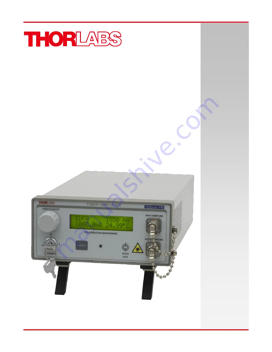
Page 8: ...cated to the left of the display The following information will be available Top Left Indicates device type EDFA Top Right Indicates the amplification band of the device This is set to 1550 nm for the EDFA100S and EDFA100P fiber amplifiers Bottom Left Indicates the pump current Bottom Right Indicates the actual temperature of the pump laser in C The system defaults to a temperature that is set at ...
Page 9: ...so be achieved by allowing the display to time out at any point in the process The display will adjust in real time to the new current setting 5 5 Turning the Fiber Amplifier Off Standby Mode By adjusting the control knob fully counterclockwise the pump current will adjust down to the threshold current and then to standby mode Disable Enable Mode The amplifier output can be turned off by pressing ...
Page 10: ... will not re enable until the ENABLE switch is pressed or until the Set Enable command is entered in the command line interface see Section 7 3 All units shipped from Thorlabs are configured with a shorting device installed in the interlock connector If you are not going to use this feature then you can leave the shorting device installed and the unit will operate normally as described throughout ...
Page 11: ...nd the power turned on configure the terminal emulator as follows Baud Rate 115 2K Bits Per Second Data Bits 8 Parity None Stop Bits 1 Flow Control None If the connection is correct you will see the following after pressing the Enter key Command error CMD_NOT_DEFINED Followed immediately by the prompt The basic structure of the interface is a keyword followed by either an equals sign or a question...
Page 12: ... the temperature and current when the arrow keys are pressed Get Step step Returns the increment used to adjust the temperature and current when the arrow keys are pressed Save Parameters save Saves target current and target temperature to EEPROM Values are restored on device startup Get Status statword Returns a string representation of an 8 bit number indicating the device s status The right mos...
Page 13: ...s please return the unit to Thorlabs for evaluation Unit does not enable when pressing the ENABLE button 1 Make sure the AC line cord is properly plugged in and the key switch is turned to the ON position 2 Check to make sure the interlock jumper is installed on the rear panel See page 10 for details Unit is enabled but there is no output 1 Check to make sure you are using the correct type of fibe...
Page 14: ...g can be cleaned using a soft slightly damp cloth Avoid using any solvents on or near the unit Keep the vent holes located on the bottom of the unit and on the rear panel free of dust buildup Restricted airflow will cause the temperature controls to operate inefficiently and in extreme cases loss of temperature control 9 2 Connector Cleaning Always clean the ferrule end of your fiber patch cables ...
Page 15: ...r firmly swipe the connector tip across the exposed cleaning strip The connector tip should be flush against the card surface i e held at a slight angle for FC APC connectors If you need additional connector cleaners Thorlabs offers the FCC 7020 Fiber Cleaning Cloth Spool To use the FBC1 Bulkhead and Connector Cleaner please refer to the instructions shipped with the FBC1 ...
Page 16: ...r Aligned to Slow Axis Polarization Extinction Ratio N A 25 dB Polarization Dependent Gain 0 2 dB N A Return Loss at Input Port 50 dB Input Output Isolation 30 dB Input Output Fiber Type SMF 28 J9 PM1550 XP Input Output Fiber Connectors FC APC Compatible 2 0 mm Narrow Key a The wavelength range over which the output power at 3 dBm input power does not fall below 18 dBm b Specified at 1550 nm Pleas...
Page 17: ... mm x 77 7 mm Weight 2 08 kg 4 58 lbs Connections and Controls Interface Control Optical Encoder with Push Button Enable Select Keypad Switch Enable with LED Indicator Power On Key Switch Fiber Connectors FC APC Compatible 2 0 mm Narrow Key Display LCD 16x2 Alphanumeric Characters Input Power Connector IEC Connector Interlock 2 5 mm Mono Jack See Chapter 6 Communications Communications Port USB 2 ...
Page 18: ...Fiber Amplifier Chapter 11 Mechanical Drawings TTN118382 D02 Rev A November 18 2016 Page 18 Mechanical Drawings Figure 5 EDFA100S Mechanical Drawing Figure 6 EDFA100P Mechanical Drawing ...
Page 19: ...rlabs products such as Pure OEM products that means assemblies to be built into a unit by the user e g OEM laser driver cards Components Mechanics and optics Left over parts of units disassembled by the user PCB s housings etc If you wish to return a Thorlabs unit for waste recovery please contact Thorlabs or your nearest dealer for further information 12 1 Waste Treatment is Your Own Responsibili...
Page 20: ...Fiber Amplifier Chapter 13 Declaration of Conformity TTN118382 D02 Rev A November 18 2016 Page 20 Declaration of Conformity ...
Page 21: ...ope thorlabs com Scandinavia Thorlabs Sweden AB Bergfotsgatan 7 431 35 Mölndal Sweden Tel 46 31 733 30 00 Fax 46 31 703 40 45 www thorlabs com Email scandinavia thorlabs com France Thorlabs SAS 109 rue des Côtes 78600 Maisons Laffitte France Tel 33 0 970 444 844 Fax 33 0 825 744 800 www thorlabs com Email sales fr thorlabs com Brazil Thorlabs Vendas de Fotônicos Ltda Rua Riachuelo 171 São Carlos S...
Page 22: ...www thorlabs com ...