© 2011 Thorlabs
93
Operating the Beam Profiler
3.5.5
Setting up
3.5.5.1
Mechanical Setup
The Thorlabs BC1M2 Extension set for M
2
measurements is not a compact
instrument but consists of separate components which are built together. In addition,
means for beam alignment and focusing need to be ordered separately.
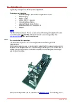
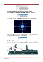
The following sketch gives an example of a M
2
measurement setup.
Beam Profiler
Laser source
Focusing lens
Translation stage with controller
USB
RS232
Control software
running on a PC
Mounting the translation stage on a table
It is highly recommended to mount the translation stage onto a table to ensure a fixed
position and repeatable measurements.
Use the
base plates
delivered with the BC1M2 Extension Set to mount the stage
onto an optical table.
Mounting the BC106 Beam Profiler to the translation stage
First mount the Beam Profiler onto the adapter plate by using the appropriate M6x10
screw delivered with the BC1M2 Extension Set. Therefore put the BC106 Beam
Profiler into the designated bracket and push it slightly against the stop at the front.
This guarantees orthogonal to the moving direction of the translation stage
adjustment of the camera sensor. Then fix the screw.
Summary of Contents for BC106-UV
Page 1: ...2011 Operation Manual Thorlabs Beam Beam Analyzing Software BC106 VIS BC106 UV ...
Page 2: ...Version Date 4 0 11 04 2011 2011Thorlabs 2011Thorlabs ...
Page 76: ... 2011Thorlabs 74 Thorlabs Beam 4 0 Example ...
Page 157: ... 2011Thorlabs 155 Appendix 7 4 4 Drawings 7 4 4 1 BC106 UV ...
Page 158: ... 2011Thorlabs 156 Thorlabs Beam 4 0 7 4 4 2 BC106 VIS ...
Page 159: ... 2011Thorlabs 157 Appendix 7 4 4 3 BC1M2 Mounting Adapter ...
Page 160: ... 2011Thorlabs 158 Thorlabs Beam 4 0 7 4 4 4 Translation Stage VT 80 ...
Page 167: ......

