


© 2011 Thorlabs
137
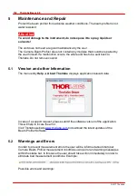
Maintenance and Repair
6
Application Note
This chapter contains the background knowledge about the measurement methods
of beam profiles.
Beam profiles can be characterized by a number of different parameters. Our aim
was to offer measurement of all usual beam parameters based on ISO11146-1.
In the following sections detailed explanations are given to the measured
parameters.
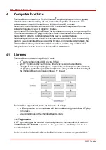
6.1
Ambient Light Correction
Thorlabs Beam software implements a unique Ambient Light Correction (ALC)
method.
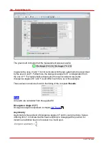
You may have noticed, that the correction process takes a certain time, shown on the
progress bar:
After the laser beam has been blocked, the ALC records a number of images at
different exposures and averages them. Intermediate values are being interpolated.
This allows a precise calculation of the camera's baseline with ambient light valid at
different exposure times.
An outstanding property of the ALC is, that the baseline is determined as an
average of the ambient light "noise" and does not clip negative intensity values. If the
baseline is defined in a way, that negative values are possible, the ambient light
sums up to a value close to Zero. This turns out in a significant advantage particularly
for M² measurements - the 4 values can be determined with a higher accuracy, as
in this case the interference of ambient light is nearly eliminated.
6.2
Coordinate systems
Lab System
The lab system (AKA reference system) of coordinates is based on the true X and Y
coordinate orientation of the CCD camera chip (X = lines, Y = columns).
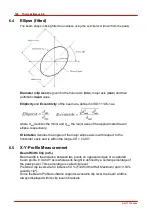
Transformed System
The transformed system of coordinates is based on the calculated beam axes
(minor and major axes for elliptical fit or for 4 beam diameter).
Summary of Contents for BC106-UV
Page 1: ...2011 Operation Manual Thorlabs Beam Beam Analyzing Software BC106 VIS BC106 UV ...
Page 2: ...Version Date 4 0 11 04 2011 2011Thorlabs 2011Thorlabs ...
Page 76: ... 2011Thorlabs 74 Thorlabs Beam 4 0 Example ...
Page 157: ... 2011Thorlabs 155 Appendix 7 4 4 Drawings 7 4 4 1 BC106 UV ...
Page 158: ... 2011Thorlabs 156 Thorlabs Beam 4 0 7 4 4 2 BC106 VIS ...
Page 159: ... 2011Thorlabs 157 Appendix 7 4 4 3 BC1M2 Mounting Adapter ...
Page 160: ... 2011Thorlabs 158 Thorlabs Beam 4 0 7 4 4 4 Translation Stage VT 80 ...
Page 167: ......