background image

Kalypso Reference Manual

341

M/E Menus


Matte Menu and Mix Through Video Transitions

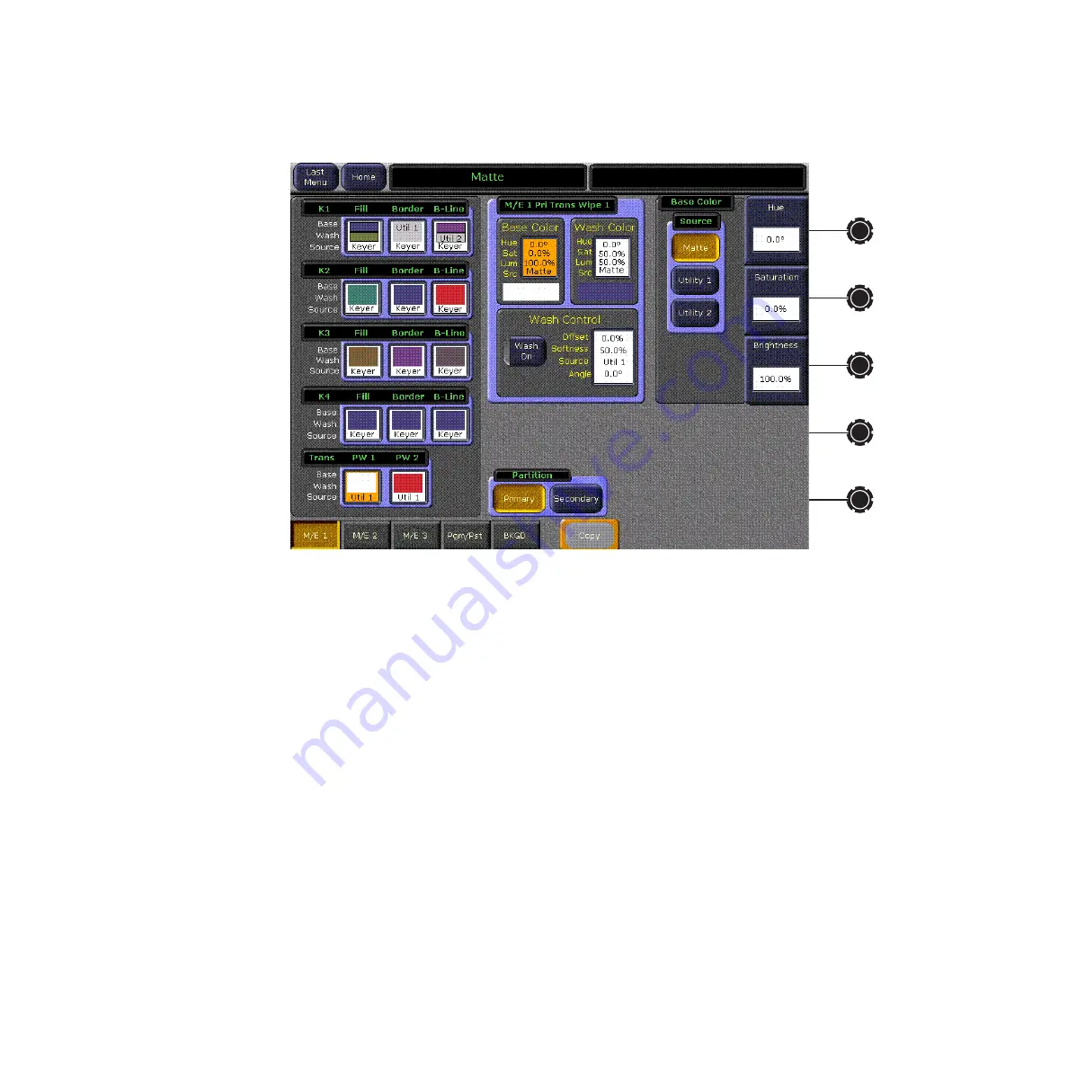
Figure 235.  Set Up White Matte

To use a matte as intermediate video, select the 

Matte

 button in the Base 

Color – Source pane on the right of the menu. Use the matte controls to set 
the desired matte settings for the intermediate video. 

Note

Intermediate video is always that defined for the primary or secondary parti-
tion Trans Wipe 1 border. 

To use Utility bus video, select the 

Utility 1

 or 

Utility 2 

button. Then select the 

desired Utility video source either on the Main panel with the 

Alt Buses


source select modifier button, or use the M/E Source Select menu. 

Summary of Contents for Grass Valley Kalypso Classic

Page 1: ...Kalypso VIDEO PRODUCTION CENTER Reference Manual SOFTWARE VERSION 11 0 071817605 MARCH 2005...

Page 2: ...lutions to problems and troubleshooting efforts can be found by searching our Frequently Asked Questions FAQ database Software Downloads Software updates drivers and patches can be down loaded Region...

Page 3: ...and Options 20 External Interfaces Supported 20 System Components 20 Control Surface 21 4 M E Kalypso System 23 4 M E Main Panel 23 Menu Panel 26 Local Aux Panel 29 Removable Media Drives 30 2 M E Ma...

Page 4: ...E Status Displays 74 M E Status Information 74 Additional Keyer Status Information 75 Transition Information 75 Lever Arm Progress Bar 76 Transition Subpanels 77 Main Transition Controls 78 Keyer Tra...

Page 5: ...Transform Subpanel 127 Joystick 128 Joystick Delegation 128 Transform Buttons 129 Axis Buttons 131 Inactive Buttons 131 Macros Subpanel 131 Macro Delegation 132 Show Macro 132 Macro Record 132 Insert...

Page 6: ...l 153 Source Selection 154 Transition Subpanel 155 Transition Rate Readout 155 Lever Arm Sync Arrows 155 1 M E Main Panel Reset 156 Macros Subpanel 156 DPOP 156 Inactive Controls in Release 11 0 156 S...

Page 7: ...All Links Menu 187 User Prefs Menus 187 Button Mapping Menus 188 Aux Delegation Mapping Menus 190 Shift Preferences Menu 191 Source Display Menu 192 Clip Hi Lo Preferences Menu 193 Double Press Altern...

Page 8: ...ile Operations Menu 232 Status Diags Versions Menu 234 Memory Usage 234 Grab SW Diag Data 234 External Device E MEM Menus 235 External Device Enables Menu 235 Devices Pane 236 Device Statuses 236 Edit...

Page 9: ...Preset Transfer to Program 281 Still and Clip Selection 281 Unload Output Button 282 Start at KF Button 282 Folder Browser 283 Playback Controls 284 Playback Menu Position and Crop Controls 284 Still...

Page 10: ...ers Pane 320 Transform Engine Advanced Effects Option Kalypso HD Duo Only 320 Glow Menu 321 Effects Send Activation 321 Glow Pane 321 Glow Matte Pane 322 Glow Path Pane 322 Defocus Menu 323 Defocus Pa...

Page 11: ...65 Introduction 365 1 M E Built In Menu Features 365 DPOP with Separate Menu Panel 365 Menu Joystick Delegate Subpanel 366 Built In Menu Delegation and Navigation 366 Valid Menu Delegation Combination...

Page 12: ...Menu 380 Borderline Menu 381 Current Next Priority Menus 381 Matte Menus 382 Matte Top Menu 382 Matte Point Of Use Delegation Menu 383 Wash Generator Select Menu 384 Background Wash Adjust Menu 384 E...

Page 13: ...owledge of the system The Kalypso Reference Manual contains comprehensive and concise informa tion about the Kalypso panel controls and menus Refer to this manual to learn the functions of specific Ka...

Page 14: ...are The Kalypso Emergency Bypass Option Instruction Manual shipped with the Emergency Bypass option hardware contains information about installing configuring and operating this option The Kalypso Zod...

Page 15: ...e supporting either high defini tion or standard definition video Kalypso HD and one supporting only standard definition video but able to be upgraded to operate in either stan dard or high definition...

Page 16: ...tputs each up to 48 total outputs Source Name displays for M E 1 2 and 3 Chromatte Advanced Dual Chroma Keyer adds two floating chroma keyers able to be assigned to any keyer in the system at any time...

Page 17: ...the 4 M E Kalypso system with the following differences One full featured M E bank and one full featured PGM PST bank on the Main panel 24 Source Selection buttons on each M E bus row and Local Aux pa...

Page 18: ...Effects Send internal only available on every key bus Unlimited re entry Look ahead and other preview modes Touch screen Menu panel Local Aux panel with source name display standard E MEM 100 registe...

Page 19: ...e Loader application for image transfer to and from PCs KlipCache for SuperStill increases cache storage capacity to 4 5 GB DoubleTake permits two completely independent M E composites in a single M E...

Page 20: ...alling the KAL UPG DUO HD S software upgrade Kalypso Duo systems also support the Emergency Bypass option External Interfaces Supported All Kalypso systems support the following control interfaces and...

Page 21: ...ultiple Control Surfaces allowing more than one operator to control some or all of the Kalypso system A Control Surface consists of at least two components a Main panel and a Menu panel The 4 M E has...

Page 22: ...YPSO REMOTE AUX PANEL REM OT E AUX P ANEL 1 M E Main Panel Menu Panel option Remote Aux Panel option Zip Drive customer supplied option 0619_08_73_r1 Menu Panel Local Aux Panel 4 M E Main Panel Zip Dr...

Page 23: ...the Kalypso Processor and to other components of the Kalypso Control Surface are located on the rear of the Main panel Figure 6 0618_00_16_r7 Source Selection 4 M E Status Displays 4 E MEM Subpanels...

Page 24: ...rate Menu panel and Local Aux panel Figure 5 Late Model 4 M E Main Panel Inside View Menu Panel Power Local Aux Bus Power Panel Diagnostic Panel LAN Satellite Control Panels 12 Not Used AC In 8162_00_...

Page 25: ...Touchscreen Menu Diagnostic Panel Diagnostic Panel LAN Menu Display SVGA Video Out Satellite Control Panels 12 Facility LAN Menu Controls AC In 0618_06_142_r0 SATELLITE PORTS TRANSMIT RECEIVE 8 8 8 8...

Page 26: ...to additional system controls that gener ally do not require real time adjustment The Menu panel can be installed above or to either side of the Main panel and should be oriented so the screen directl...

Page 27: ...ttern for Adjustable Freestanding Console Bracket or Articulated Arm Serial Ports 1 6 in 41 mm 4 3 in 109 mm Hole pairs top and bottom for Flush Mount kit Hole pair for Adaptable Mounting Bracket 5 US...

Page 28: ...receives its power from the Main panel An optional brick style external power supply is available that allows the Menu panel to be powered independently from the Main panel Figure 12 This same type o...

Page 29: ...11 11 Aux Aux 12 12 Still Still Store Store Aux Aux 13 13 PVW PVW Pri Pri M E 1 M E 2 M E 3 Pgm Pgm Pst Pst Shift Shift Un Un Shift Shift Hold Hold Near Near Side Side Far Far Side Side Key Key Split...

Page 30: ...dia Drives are provided depending on Kalypso model Late model Kalypso systems ship with a USB 250 MB Zip drive that connects to the Menu panel and a CD ROM drive built into the Menu panel If the Enhan...

Page 31: ...panel 0618_01_87_r0 Source Selection Local Aux Subpanel M E Status Displays 2 E MEM Subpanel Keyers Masks Subpanels Mattes Copy Swap Subpanels Master E MEM Subpanel Effects Run Subpanel Transition Su...

Page 32: ...el Diagnostic Emergency Bypass Mixer Emergency Bypass Router Menu Panel Power Local Aux Bus Power AC In LAN Redundant DC Power In Panel Diagnostic Panel LAN Satellite Control Panels 12 Not Used 0618_0...

Page 33: ...ixer Emergency Bypass Router Panel Diagnostic Panel LAN Menu Display SVGA Video Out Satellite Control Panels 12 Inactive on modified systems Menu Panel Power Local Aux Bus Power Facility LAN Menu Cont...

Page 34: ...K4 A U1 B U2 K1 K3 K2 K4 A U1 B U2 M E 1 Mix Key 4 Key 3 Mix Bank Edit Eff Detent Center Key 2 Mix Key 1 Mix Lock Learn Master Undo Cut Trans Auto Mix On Bkgd Wipe Sec 1 Key 2 Key 3 Key PVW Black Pres...

Page 35: ...n a console Figure 21 Kalypso 1 M E Main Panel Rear View AC LINE 1 AC LINE 2 LAN SATELLITE PANEL DIAGNOSTIC 0 NORMAL RESET COM 1 COM 2 AC LINE 1 AC LINE 2 LAN SATELLITE PANEL DIAGNOSTIC 0 NORMAL RESET...

Page 36: ...x Panel Figure 23 KAL 24AUX2 2 RU Remote Aux Panel Figure 24 KAL 24AUX3 3 RU Remote Aux Panel REMOTE AUX PANEL 1 1 2 3 4 5 6 7 8 9 10 10 11 11 12 12 13 13 14 14 15 15 16 16 ON ON AIR AIR 1 2 3 Pgm Pgm...

Page 37: ...UX2 2 RU Remote Aux Panel COMMUNICATIONS BUS SHIELD DC POWER JOYSTICK OVERRIDE 64 32 16 8 4 2 1 8 4 2 1 FORCE HIGH TALLY MODE TEST ADDRESS PANEL OFF ON 0619_04_65_r0 DC Power Test Mode Panel Address a...

Page 38: ...cables pro vided If located more than 3 m 10 ft from the Main panel an optional Sat ellite Panel extension kit is available that includes a brick type power supply RATED CURRENT 0 35 A CAMERA JOYSTIC...

Page 39: ...les A fully loaded system is shown in Figure 31 Figure 31 Fully Equipped Kalypso Classic Video Processor Frame Front View Door Removed CAUTION The front door of the Kalypso Video Processor must remain...

Page 40: ...J13 J14 J15 J16 SERIAL OUTPUT J1 J2 J3 J4 J5 J6 J7 J8 J9 J10 J11 J12 J13 J14 J15 J16 SERIAL OUTPUT J1 J2 J3 J4 J5 J6 J7 J8 J9 J10 J11 J12 J13 J14 J15 J16 SERIAL OUTPUT J1 J2 J3 J4 J5 J6 J7 J8 J9 J10 J...

Page 41: ...ystem supports the Still Store and Transform Engine options and up to two additional M E modules can also be added Figure 33 Standard 2 M E Kalypso Video Processor Frame Front View CAUTION The front d...

Page 42: ...J14 6 7 422 CPL SERIAL PORTS GPI COMM 1 COMM I O CONTROL PANEL LAN J1 FACILITY LAN J2 STILL STORE LAN J3 SERIAL INPUT J1 J2 J3 J4 J5 J6 J7 J8 J9 J10 J11 J12 J13 J14 J15 J16 EFFECTS SEND J1 J2 J3 J4 J5...

Page 43: ...nly two M E modules stan dard for control by the PGM PST and M E 1 banks Adding M E modules in the slots listed allows delegated control of the added M Es An addi tional Crosspoint module in slot A9 i...

Page 44: ...Engine modules are optional Figure 35 Fully Equipped Kalypso Video Processor Frame Front View Door Removed CAUTION The front door of the Kalypso Video Processor must remain closed during normal system...

Page 45: ...Ethernet LAN Connections 6 external ports 0619_08_77_r1 2 HDLC Serial Connectors for CPL Interface Diagnostic Port Timecode Reader Input GPI In GPI Out Tally 1 32 Tally 33 64 Outputs Inputs LAN Timeco...

Page 46: ...deo Processor Power Supply Front View Power connectors are located on the rear of the Video Processor Power Supply Figure 38 including a special connector for feeding power to the Video Processor Each...

Page 47: ...orage capacity of the Still Store cache Sources to be captured are selected on the Local Aux panel That source can then be grabbed repeatedly if necessary until the desired image is caught The capture...

Page 48: ...ive Post Transform Global channel on each M E and PGM PST to which the Transform Engine channels in that M E can be individually assigned Raster Cropping E MEM keyframe control Near Far Front Back wit...

Page 49: ...hnical Director can recall and run DPM effects from the Kalypso Main panel Figure 39 Basic Live Production Studio System Configuration Example Program Monitor Preview Monitor Other Monitors Program Ou...

Page 50: ...Boot Config BU Flash Tally Hard Drive Still Store Hard Drive Remote Control Surface 3 24 Crosspoint Remote Aux Panel 32 Crosspoint Remote Aux Panel Video or Key Signal Control Line Suite Boundary Cont...

Page 51: ...sources LAN Ethernet Switch Ethernet Hub 0721_02_05_r6 Remote Control Surface 1 Remote Control Surface 2 Kalypso Suite Four Control Surfaces Shot Box Facility LAN Facility LAN Video or Key Signal Con...

Page 52: ...e Boundary Button Knob Control Serial Touch Screen Control Serial SVGA SCSI SCSI Optional Keyboard Optional Mouse Menu Panel CD ROM Zip Drive Optional Future Satellite Panels 1 12 To networked image s...

Page 53: ...b Control Serial Touch Screen Control Serial SVGA SCSI SCSI Optional Keyboard Optional Mouse Menu Panel CD ROM Zip Drive Optional Future Satellite Panels 1 12 To networked image sources LAN Ethernet S...

Page 54: ...54 Kalypso Reference Manual Section 1 System Overview...

Page 55: ...ire system see Figure 44 and Figure 45 for Kalypso Classic and Figure 46 for Kalypso HD The only exception is Effects Send where the outgoing signal is routed directly to its internal or external dest...

Page 56: ...1 Program A M E 1 Program B M E 1 Program C M E 1 Program D M E 1 Preview A M E 1 Preview 2 M E 2 Standard M E 3 Standard PGM PST Standard Input Module 2 Option 17 32 Inputs Input Module 3 Option 33...

Page 57: ...d or Unshaped Video Input B Key or Shaped Video Output Module 1 Option 1 8 Dual Outputs Variable Delay 1 Variable Delay 2 Variable Delay 3 Variable Delay 4 Variable Delay 5 Variable Delay 6 Variable D...

Page 58: ...Ch 5 Ch 6 Pvw Video Pvw Key In 1 In 2 Still Store Option Eff Return Eff Send M E 1 Outputs M E 2 Outputs M E 3 Outputs M E 1 Inputs Transform Engine 1 Option 3 Video 3 Key Channels Transform Engine 2...

Page 59: ...his section describes the controls for the 4 M E Main panel and LocalAux panel and explains the differences between the 4 M E and 2 M E Kalypso system controls Kalypso menus are described in Section 3...

Page 60: ...nother button in the group will activate both functions Pressing only one button in the group will turn off any other active functions in that group If an indi vidual button is pressed when off it wil...

Page 61: ...on double press where the alter nate action displays a specific menu See page 64 for more information Button Tally The state of a panel button is indicated by the illumination of its internal tally LE...

Page 62: ...of prompt indicating the user must select one of these buttons Pressing a flashing button in this case is a form of delegation and does not change the state of the pressed button Knob Behavior The Kal...

Page 63: ...when it is selected on the Main panel Automatic delegations available are listed in Table 2 M E Keyer manual delegation buttons used to delegate the Keyers Masks subpanel Mattes subpanel and or the T...

Page 64: ...3 4 Mattes subpanel Matte menu selected keyer delegated M E 1 2 3 Pgm Pst Mattes subpanel Matte menu selected M E delegated Borderline Pst Pts Bord Matte Fill Mattes subpanel Matte menu Chr Key Keyers...

Page 65: ...conds can be entered by adding one separator For example a time of 1 second is input by pressing 1 Enter An odd field is input by pressing 1 as the last entry For example a time of one second 15 frame...

Page 66: ...ete the entry If a default value exists for an entry it can be input without typing in a value by pressing Enter The Kalypso Menu Panel also provides a touch activated keypad for entering values direc...

Page 67: ...s Figure 48 and Figure 49 These buttons control source selection on a total of 12 buses on each M E Key 1 2 3 4 Cut and Fill Background A and B and Utility 1 and 2 0618_00_16_r7 Source Selection 4 M E...

Page 68: ...each bus on the row of inter locked buttons The left source will be selected if more than one button on a row is pressed simultaneously Holding down a source select button when recalling an E MEM regi...

Page 69: ...tally when selected and on air and low tally when selected but not on air Source Select button tallys will blink when they have selected a source from the opposite shift preference for that bank For...

Page 70: ...e option is activated and an M E has been split the Pri and Sec delegation buttons on that M E are activated Pri and Sec Delegation Buttons The Pri and Sec buttons delegate the source selection buses...

Page 71: ...nes of text with the largest size displayed automatically Figure 48 on page 68 Kalypso source name displays can be configured on a bank by bank basis for different display modes Show unshifted names S...

Page 72: ...Buses source select modifier button is used to delegate a button row to its alternative bus Each key and background source buttons on each M E can control an alternate bus Table 5 Unshift Shift and Sh...

Page 73: ...on page 74 To cancel a key split either look at the M E status display to identify the key cut source or note the key fill source when Key Split is not held down then hold down Key Split and select t...

Page 74: ...reference is shown with a down or up arrow Up arrow indicates a shifted preference and down arrow indicates an unshifted preference Source Hold Keyer Hold or Bus Lock is active Internal Transform Loop...

Page 75: ...key priority of the keyer 1 4 with 1 highest priority Keyer Preset Pattern active Key type Autoselect Key or Video Key Whether a mask either Inhibit or Force mask is on or off Transition Information...

Page 76: ...r with thin lines at the limits The lever arm is represented by a wider horizontal handle that moves along with the tran sition bar during manual transitions When the lever arm is in sync with the lev...

Page 77: ...M E partition can be assigned resources keyers and wipe generators of that M E and the Transition subpanel controls the delegated partition See the separate Kalypso User Manual for more information 06...

Page 78: ...remains the on air bus The Abus selection remains the background source if this button is not selected as part of the next transi tion The Key 1 4 buttons selects the keyers that will be involved in t...

Page 79: ...s an automatic transition of a predetermined rate see Transition Rates on page 81 The button will light during the transition Pressing Auto Trans a second time during a transition stops the transition...

Page 80: ...bus will also cancel a preset black transition The source pressed on the A bus will immediately be placed on air without any keys even if the next transition had specified key changes Transition Previ...

Page 81: ...ix buttons can be used to mix a key on or off The transition will mix to the opposite state mix on if the key is off mix off if the key is on Key Mix button tallies do not indicate whether a key is on...

Page 82: ...perform a main transition For example you can start the transi tion by moving the lever off its limit and finish the transition by pressing Auto Trans The transition is completed at a rate proportion...

Page 83: ...ing on whether a matte or wipe pattern attribute is in use by that keyer When an M E Keyer delegation button changes subpanel delega tions the separate delegation buttons of the subpanels involved wil...

Page 84: ...n M E Keyer delegation button will also delegate that source selection bus for control For example holding down M E Key 3 causes the Key 1 3 bus row to be delegated to control Key 3 Sources can then b...

Page 85: ...anel Delegation determines which M E and keyer or matte is being controlled at any given time by the M E Modifiers controls Delegation is available on the individual subpanels via the M E Keyer delega...

Page 86: ...eft Horiz Right Vert Bottom Size Clip Opacity Adj Lin Hold to Preview Gain Clip Hi Soft Clip Clip Lo Size Hi Lo No No Border Border Border Border Line Line Shdw Shdw Ex Ex trude trude Out Out line lin...

Page 87: ...see Keyer Priority Buttons on page 89 Hold to Preview When setting up a key it is often desirable to see a key that is not on air or part of the next transition Holding down a Keyers Masks subpanels K...

Page 88: ...ilable via DPOP The Pst Ptn button selects Preset Pattern which cuts the hole in the back ground using an internal wipe pattern generator or Utility Bus video rather than a source s key cut signal The...

Page 89: ...se the video signal defines the character area and usually produces a better result Keyer Priority Buttons The Current Prior and Next Prior buttons are inactive in Release 11 0 except they DPOP to the...

Page 90: ...ates edges of the keyed area many times The number of replications is adjustable with the Border Position Direction knob The same knob controls the extrude direction when the Extrude button is held do...

Page 91: ...eyer delegated in the Keyers subpanel A high button tally indicates which mask is being con trolled If the other mask is also active its delegation button will low tally Knob control of the opacity of...

Page 92: ...jacent Keyers subpanel The Masks subpanel knobs control different parameters depending on the type of mask When Wipe C1 Wipe C2 or Keyer Wipe is selected the following knobs are also available Figure...

Page 93: ...es button is only active when the Box mask source is selected Preset Pattern can also be adjusted using these mask controls Figure 59 Box Pattern Mask Knob Parameters with Separate Edges 0618_00_77_r2...

Page 94: ...ntrol is not available for utility masks Figure 60 Utility Mask Knob Parameters 0618_00_79_r1 Masks Top Soft Gain Left Horiz Right Vert Bottom Size Clip Inhib Inhib Mask Mask Sep Sep Edges Edges Keyer...

Page 95: ...oftness wipe pattern generators and other controls are available to adjust how the colors or images blend with one another 0618_02_12_r0 M E Modifiers Mattes Rotate Wash Geometry Base Wash Fill Hue Te...

Page 96: ...These buttons select which matte of that M E s keyer will be controlled by the Wash Geom etry and Base Wash Fill group buttons and knobs Borderline and PstPtn Border share one Wash Geometry pattern g...

Page 97: ...delegation buttons above The Util 1 and Util 2 buttons select video fill from a utility bus Manual source selection for each utility bus is accomplished with the Alt Buses modifier button see Alt Buse...

Page 98: ...points of use using the same wipe pattern generator Other parameters size offset softness affect only the wash and do not affect other wipe pattern generator points of use The parameters for each wash...

Page 99: ...18_02_05_r0 M E Modifiers Mattes Rotate Wash Geometry Texture Offset Size Clip Softness Gain Key Only Flat Flat t t C 2 C 2 Wipe Wipe C 1 C 1 Wipe Wipe Utility Utility 2 Utility Utility 1 t t Keyer Ke...

Page 100: ...ip and Gain of the video that specifies the wash Figure 65 Figure 65 Utility Wash Controls 0618_02_03_r0 M E Modifiers Mattes Rotate Wash Geometry Texture Offset Size Clip Softness Gain Key Only t t t...

Page 101: ...ration is completed using the delegation buttons in the Mattes subpanel 0721_08_82_r0 M E Modifiers Mattes Rotate Wash Geometry Base Wash Fill Hue Texture Saturation Brightness Offset Size Clip Softne...

Page 102: ...utton tallies will go off and are then restored to the previous Matte modifier button tally state Undo Button The Undo button in the Copy Swap subpanel reverses a copy or swap oper ation that has been...

Page 103: ...he E MEM subpanel also provides Lock Sequence and Effect Dissolve capabilities On the 4 M E Kalypso system M Es 1 2 and 3 are equipped with this subpanel Figure 67 Figure 67 E MEM Subpanel All the fun...

Page 104: ...ation for other buttons The actual operating mode is determined by what other button is pressed next The first operating mode is used to specify a bank number Pressing the Bank button so it lights cau...

Page 105: ...nks 4 through 7 are accessed by pressing the appropriate bank button twice in rapid succession For example the following button presses will recall a register from bank 1 Bank 1 5 register number The...

Page 106: ...g the following procedure Parentheses indicate optional values Lock Learn Seq bank selection register delay time bank selection register delay time Lock Learn The Seq button may be pressed before Lock...

Page 107: ...ecalled as an effect dissolve with the following proce dure This is useful for testing an effect before it is learned as an effect dis solve Parentheses indicate optional use of one of the bank select...

Page 108: ...s used with Learn Get and Put operations to represent the next available register the default The unshifted Undo button is also used for Sequence and Effect Dissolve operations to represent the colon...

Page 109: ...ersion and display the result in seconds frame field format Decimal values for other non time parameters are also input on the Master E MEM subpanel with the numeric keys the Undo button for the decim...

Page 110: ...characters If a register on another M E or PGM PST has been recalled using Recall From the first two characters will indicate the M E it came from Figure 68 E MEM Readout Display of Current Effect Th...

Page 111: ...o Go To Time Time Knob Knob Set Set Level Level Start Start KF KF Time Time KF KF Dur Dur Go To Go To KF KF Trans Trans Rate Rate Eff Eff Dur Dur Sel Sel All All M E M E 1 M E M E 2 M E M E 3 Ind Ind...

Page 112: ...de on page 174 and is saved and loaded as a Suite Preference See the separate Kalypso User Manual for 300 Mode operating information In general you will need to decide which Master E MEM operating mod...

Page 113: ...turn off an Enabled level by pressing its button so its tally goes off E MEM Level Assignments Each Enable button can actually be configured to control several E MEM levels or an enable group Pressin...

Page 114: ...fix button before Enter The difference is that pressing Clear Entry keeps the keypad delegated to the numeric entry while pressing the prefix button restores the keypad to register recall Detent Butto...

Page 115: ...ts rate data entry for PGM PST and cannot be used to enter rates for an individual M E E MEM See Trans Rate Button on page 108 The following prefix buttons are only on the Master E MEM keypad Knob Set...

Page 116: ...specified Get register will be copied to the appropriate level in each of the current effect registers For example suppose M E 1 is using register 1 as its current effect and M E 2 is using register 2...

Page 117: ...on in the work buffer to one second KF Time The KF Time button is used to reposition the keyframe the cursor is located on to a specified time in the effect Pressing this button activates the function...

Page 118: ...the button is lit before you learn the register Note that learning the register stores the current set tings in the register so all the levels must be in the proper state before the learn To recall an...

Page 119: ...previously defined settings replace the current settings The Default Keyframe is a single group of settings defining a particular switcher state These settings are copied to the work buffer when the w...

Page 120: ...e M E status display clears all the work buffers parameters except those associated with source memory for each held down keyer The Master E MEM enables have no bearing on this operation Double pressi...

Page 121: ...of the previous keyframe is increased to fill the time Cursor Button Group The cursor buttons affect use of the run and edit cursors These buttons are interlocked One or the other will always be high...

Page 122: ...the path This maintains the relative alignment of all the delegated timelines The cut keyframe information is saved to the clip board overwriting any existing information Cut is inactive when the cur...

Page 123: ...an be made using the Timeline menu see page 264 You can also press Master E MEM Learn then Modify to update the Master E MEM effect header This can be used for example to change only the Auto Recall s...

Page 124: ...nformation does not change In a standard Learn operation all existing keyframe data is overwritten with a single keyframe and new header information is saved You can use Learn Modify to update E MEM r...

Page 125: ...ions on any Kalypso system bus including the Aux buses When on no source on any bus will change when an E MEM is recalled When off sources may change during an E MEM recall if no other types of hold a...

Page 126: ...the lever arm is active When inactive accidental move ments of the lever arm will not affect the currently loaded effect Progress Bar LEDs illuminate to report the relative progress of the effect The...

Page 127: ...the delegated parameter values Parameters can also be delegated to the Master E MEM subpanel for exact value entry 0618_02_10_r0 Transform M E 1 M E 2 M E 3 Pgm Pgm Pst Pst Wipe Wipe C1 C1 Wipe Wipe C...

Page 128: ...tion can be required to access and control a specific set of parameters Different types of delegation are avail able depending on the parameters being controlled Joystick delegation is similar to that...

Page 129: ...at button and deselects all others in that group Pressing down more than one dele gation button at the same time delegates the joystick to control multiple objects simultaneously The Key 1 4 buttons s...

Page 130: ...between keyframes Note Following broadcast conventions moving the Joystick forward or back along the Joystick s Y axis rotates the top of the picture forward or back a rotation about the X reference...

Page 131: ...enter value to the del egated parameter Pressing and releasing the X Y and Z buttons transfers the current trans form parameter to the Master E MEM subpanel keypad The Master E MEM subpanel keypad may...

Page 132: ...keyer The Macro Deleg button will dim tally in this state Pressing the Rec Delete Pre Attach Repl Attach and Post Attach buttons when macro mode is not on automatically activates macro mode and illum...

Page 133: ...allow entry of longer delays The Insert Delay button remains on until pressed again latched mode to permit multiple button selections The Insert Delay button is only active when a macro is being reco...

Page 134: ...On a 2 M E Main panel however delegating a bank essentially creates a different set of buttons This means on a 2 M E Main panel you can attach one macro to the left most button when M E 1 is the dele...

Page 135: ...ns Holding down M E 1 Rec initiates macro Record mode and delegates the keyer row to macro operation With the button held down select a macro register button to record into and then release the M E 1...

Page 136: ...on feature at the same time if desired The result will depend on the device s capa bilities and what has been loaded on it The DDR will run its clip and the still store will run its programmed animati...

Page 137: ...t was last commanded to do As a simple example a playing device will continue to play as the delegation changes This also applies to mode selections like Auto Start which will start a device when it g...

Page 138: ...en the current clip does not appear on the readout during browsing the Cue Load button will go low tally indicating you can load a different clip Pressing Cue Load at this time will load the currently...

Page 139: ...el readout also displays the current bus delegation for machine control while Set Deleg is held down Gang Roll The Gang Roll feature permits rolling multiple external devices with a single command Dev...

Page 140: ...utput of that M E This second output is switchable to display outputs B C or D of that M E with B as the default When the Still Store button is selected holding down Alt PVW displays the cut signal of...

Page 141: ...ections on this bus when the PVW Pri button is not selected on the Preview subpanel will still change the output but it will not be visible on the switched preview output since it will be displaying a...

Page 142: ...roup Source select buttons on the Local Aux panel never flash When an Aux bus has been configured as an Aux pair the Key Split button is held down to select the source on the B side of the pair The Lo...

Page 143: ...p disk used for saving and loading configuration and effect files The basic Kalypso system also houses two hard drives One drive supports the Menu panel display and resides in either the Enhanced Menu...

Page 144: ...ptions for more information Source Selection The 2 M E Main panel has 24 source selection columns with source name displays instead of the 32 columns on the 4 M E Main panel The Keyer Copy special fun...

Page 145: ...Figure 82 Figure 82 2 M E Bank Delegation Subpanel The buttons in the M E Bank Delegate section delegate the M E bank to control that selected M E The M E bank cannot control PGM PST The buttons in th...

Page 146: ...aster E MEM panel to the desired E MEM levels Or you delegate the M E bank to the M E you wish to control and perform the E MEM action from that location Figure 83 2 M E Master E MEM Subpanel M E Modi...

Page 147: ...rt of the panel Figure 85 See Macros Subpanel on page 131 for specific information Figure 85 2 M E Macros Subpanel 0618_01_89_r1 Macros Attach Attach Enable Enable Show Show Attach Attach Pre Pre Atta...

Page 148: ...Side Key Key Split Split Far Far Side Side Shift Shift Un Un Shift Shift Hold Hold Near Near Side Side Key Key Split Split Far Far Side Side Aux Aux 12 12 Still Still Store Store Aux Aux 13 13 PVW PV...

Page 149: ...K3 K2 K4 A U1 B U2 M E 1 Mix Key 4 Key 3 Mix Bank Edit Eff Detent Center Key 2 Mix Key 1 Mix Lock Learn Master Undo Cut Trans Auto Mix On Bkgd Wipe Sec 1 Key 2 Key 3 Key PVW Black Preset Trig Trans 4...

Page 150: ...e 1 M E panel and the E MEM subpanel operates the same as an individual M E E MEM on a 2 or 4 M E Kalypso Main panel When Pgm Pst is selected the Kalypso system Pgm Pst will be controlled by the 1 M E...

Page 151: ...ttons The Enable button for the M E being controlled illuminates However this lit button does not indicate Master E MEM is delegated to that M E The lit button and the other Enable buttons cannot be t...

Page 152: ...ues are entered in seconds frames field with the default entry being frames When entering a transition rate on the currently delegated bank the duration in frames is displayed in the Tran sition subpa...

Page 153: ...for information about using this subpanel and its built in menu 0721_14_05_r1 Menu Joystick Delegate Edit Eff Detent Center X Y Z M E M E M E 1 2 3 Key 1 3 Key Key 2 4 Key F1 Up F2 F3 F4 F5 More Bkgd...

Page 154: ...s displays The Shift bus indicators for each button row indicates whether that row is in shifted source selection mode Figure 91 Source Selection 0721_14_03_r0 Source Select Modifiers K1 K3 K2 K4 A U1...

Page 155: ...r arm is not in sync with the logical transition The arrow indicates which direction the lever arm needs to be moved to regain sync Once back in sync the arrow indicator goes out Both sync arrows illu...

Page 156: ...om mands are issued to the Menu IP address configured on the 1 M E panel Note The 1 M E Main panel should not be configured with the IP address of the principle 4 or 2 M E Menu panel DPOP actions on t...

Page 157: ...duction the operator spends most of his time working directly on the Main and Local Aux panels The Menu panel is used extensively for setup and effects cre ation CAUTION Do not install unauthorized ap...

Page 158: ...play various menus on the touch screen Only one menu button can be selected at a time The menu state as it was last used will be dis 8162_00_01_r0 Fan CD ROM Touch Screen Display Soft Knobs 5 Hold to...

Page 159: ...s active the touch screen displays the parameter name and its current value on a data pad Figure 96 The parameter can be adjusted by turning the knob or the data pad can be touched to bring up a numer...

Page 160: ...an object and when touched bring up additional controls and information for that object In Figure 97 the data pad for M E 1 Keyer 1 has been selected causing the rest of the screen to display setting...

Page 161: ...s actu ally a form of delegation Touching these buttons will not change any actual Kalypso system settings so they can also be safely touched at anytime to explore the menus Touch buttons can control...

Page 162: ...gold Mode Selection Each keyer has several types of operation one of which can be chosen with the Mode Selection touch buttons Selecting one of these touch buttons deselects the others they are interl...

Page 163: ...t a pattern in the wipe menu To make menu navigation easier a menu access button can be included on one menu that links to a different related menu Numeric Keypad Touching a soft knob pad or other sin...

Page 164: ...items You can also drag the white handle to quickly scroll through the entire list on some menus Some menus have two scrolling lists used to associate an item in one list to an item in the other list...

Page 165: ...he Kalypso system the screen parame ters and organization will vary but the basic principles previously described are followed In general to learn menu capabilities you can touch the screen where you...

Page 166: ...ble 7 lists the purposes of each active menu selection button Table 7 Menu Selection Button Functions Menu Buttons Purpose Daily Setups User and Suite Preferences configuration including Profiles and...

Page 167: ...to access the bottom margin of the screen to pull up an application selection bar The Alt Tab key stroke combi nation can be used to cycle through open applications Exit Menu Brings up a dialog box t...

Page 168: ...menu is accessed by touching Daily Setups Save Load Figure 103 Figure 103 Daily Setups Save Load Menu User Profiles contain user preference settings that can change the behavior of a control surface...

Page 169: ...of a Kalypso system This allows operators to quickly customize the behavior of the panels and or to prepare for different shows without having to alter indi vidual preference settings Profiles saved t...

Page 170: ...u The Preview Prefs menu is used to activate preview screen overlays The menu is accessed by touching Daily Setups Suite Prefs Preview Prefs Figure 105 Figure 105 Preview Pref Menu The following overl...

Page 171: ...re These guide lines can be used to help position art cards or other objects Default Keyframe Menu The Default Keyframe menu is used to learn the current Kalypso panel state to the system s Default Ke...

Page 172: ...ese levels have Enable buttons in the Master E MEM subpanel M E 1 3 PGM PST Misc 1 7 etc The other four levels are used for M Es split with the DoubleTake option E MEM sublevels offer independent E ME...

Page 173: ...panes on the right The current Enable button assignment is displayed in each pane s data pad Some of these panes scroll to display additional available levels which can vary in number in different Kal...

Page 174: ...Learn operations store the register numbers of the indi vidual M Es allowing the recall of different combinations of M E registers with a single button press See Master E MEM Operating Modes Normal Mo...

Page 175: ...on Key 1 on the PGM PST A bus Video Settings Menu The Video Settings menu is used to set video standards to be used by the Kalypso system This menu is accessed by touching Daily Setups Suite Prefs Vid...

Page 176: ...p controls adjust cropping when individual Transform Engine channel crop is turned off Individual Trans form Engine cropping is used to adjust for variations in individual sources SMPTE RP 187 establi...

Page 177: ...ut will be edited and is compatible with most video editing systems that use the frame boundary for edits This setting is essential however when controlling external devices like DDRs that execute com...

Page 178: ...ce One Logical source is always selected though it may be scrolled out of view Logical Source Name Definition Each logical source has a Logical Name and a Logical Nickname data pad associated with it...

Page 179: ...uching an Engineering source button associates that source to the cur rently selected Logical source You can also select No Source in which case the system substitutes black whenever that Logical sour...

Page 180: ...r to the text or the back ground One example of using these tri color displays is to make the names of all the cameras appear green all the character generators appear yellow and the network feeds app...

Page 181: ...ce memory settings will change as different sources are selected on that bus When disabled green indicator off the current key type and source memory settings will not change when different sources ar...

Page 182: ...d the new Source Memory will be immediately applied to the Current Work Buffer While Source Memory is active Source Memory will immediately be updated to reflect changes to the Current Work Buffer Whe...

Page 183: ...y Drop Menu The Key Drop menu is used to automatically drop selected key signals when an on air hot cut occurs Each M E has its own set of Key Drop con trols The menu is accessed by touching Daily Set...

Page 184: ...c instructions on how to use the Bus Linking feature Figure 115 Bus Linking Menu The Bus Linking menu has two main panes a Controlling bus pane on the left and a Linked bus pane on the right Controls...

Page 185: ...define no bus link Only valid buses will be displayed Unavailable buses those already linked to other buses appear grayed out Touching a bus button selects that bus for that pane When a bus is selecte...

Page 186: ...g the Display Shortcut Menu button brings up a menu that can help reduce the time required to build Link Mapping tables Figure 117 Figure 117 Bus Linking Shortcut Menu The current Controlling Bus and...

Page 187: ...s User Preferences are defined by individual operators to customize system parameters to match their work flow methods Each control surface has its own set of User Preferences These preferences apply...

Page 188: ...source to button mapping if desired The Local Aux panel can also have different button mappings as well as each Remote Aux panel When Local is selected a Banks pane is displayed permitting the selecti...

Page 189: ...emote is selected a Remote Panels panel appears permitting selec tion of multiple remote panels Figure 120 Figure 120 Source Button Mapping Menu Remote Panel Type Selected See Button Mapping in the Ka...

Page 190: ...l has 13 Aux bus delegation buttons that can be used to control 13 Aux buses at a time Multi destination Remote Aux panels also have Aux bus delegation buttons More than 13 Aux buses are available on...

Page 191: ...ching Daily Setups User Prefs Shift Prefs Figure 122 Figure 122 Shift Preferences Menu Note The Shift Prefs and Source Display menu settings should match so each shifted bank displays shifted source n...

Page 192: ...y Setups User Prefs Source Display Figure 123 Figure 123 Source Display Menu Note The Source Display and Shift Prefs menu settings should match so each shifted bank displays shifted source names by de...

Page 193: ...The Clip and Gain knobs on the Kalypso system Main panel and Menu panel can control either Clip and Gain or Clip Hi and Clip Low depending on the preference set Different knob preferences can be appl...

Page 194: ...quickly The first press will still shows the original source then the second press selects the alternate source Because the original source flashes briefly this selection method is not available on th...

Page 195: ...ystem Engi neering Setups and loading an Eng Setup file will be permitted 1 Use the soft knob or touch the Login Time data pad and enter a time duration for the EIC session If no time is entered a def...

Page 196: ...settings Logging in under a different identity is necessary only for the following reasons Configuring User Prefs for a control surface lacking its own Menu panel like a 1 M E Main panel Managing reso...

Page 197: ...ortcut If while in an Engineering Setup menu you attempt to make a change when not logged in as the EIC the EIC login popup appears Figure 128 allowing you to login without having to navigate to the D...

Page 198: ...ompo nents For name pane on the left The scrolling portion of this pane has buttons for the logical components of that suite on the left and lists the physical resources acquired by that suite on the...

Page 199: ...source is not acquired and is not desired Rather than assigning specific physical components for Transform Engines or Chroma Keyers the number of resources to acquire are specified for these component...

Page 200: ...elegated Logical component on and off The Acquire Any button acquires the first available resource matching that component type for the currently delegated component The Acquire Specific button permit...

Page 201: ...ave been acquired or are avail able for the action The buttons in the lower Global pane control acquisitions for all logical components not just the delegated one This is the fastest mechanism to acqu...

Page 202: ...making all the resources available to the other suite Configuration Data The desired resource list is part of Suite Preferences This data is saved and loaded as part of a Suite Profile or Suite Pref d...

Page 203: ...ering Setup information An Engineering Setup file contains settings that are critical to system operation including source definitions output assignments and external device configurations Responsibil...

Page 204: ...T desktop are not shown The Open button opens the selected folder or drive Files cannot be opened The Copy button initiates a Copy Paste action The Paste button completes the Copy Paste action The Del...

Page 205: ...on Figure 132 Figure 132 Source Definition Menu The soft knobs on the right can be used to scroll through the source list and assign inputs Touching these data pads allows direct numeric input Input n...

Page 206: ...specific pair of physical output connec tors on the frame Touching a data pad selects it colors it gold and the rest of the screen will show information and settings for only the selected item On the...

Page 207: ...used to assign the currently selected output to a suite The default setting is Suite 1 Note Outputs assigned to Suite 2 will go to black if a Kalypso system configured for Multi Suite operation is se...

Page 208: ...settings required to use the unique features of that device DDRs VTRs and DPMs are associated with sources while GPI and PBus devices are not A new logical device can be created and existing devices...

Page 209: ...Eng Setups Menus Touching an already defined item in the scrolling Device List on the left brings up information for that device Figure 136 shows the settings for a Krystal DPM Figure 136 Port Device...

Page 210: ...Device The AMP Serial feature is a software enabled option available only when the feature has been activated After a source related logical device have been defined it can be assigned to a source in...

Page 211: ...rnal tally lights The menu set also allows the user to map Engineering sources to the tally relays See the separate Kalypso Installation and Service Manual for detailed informa tion about tally config...

Page 212: ...ual Section 3 Menus Tally Relay Assignments Menu Touch Eng Setup Tally Relay Assign the Relay Assign button is in the Function pane to access the Tally Relay Assignments menu Figure 139 Figure 139 Tal...

Page 213: ...IP Address es the Kalypso system will use to communicate to the external router The Connection Status indicator is red when communication is not detected and is green when communication is established...

Page 214: ...e Menu panel will use to communicate with the Video Processor frame and optional Still Store and set the IP addresses that the Video Processor frame will use when in Multi Suite mode to communicate wi...

Page 215: ...e Menu panel reset before the Menu panel will use this different IP address to communicate with a Kalypso Still Store Suite Panes The Suite 1 and Suite 2 panes have datapads that permit the naming of...

Page 216: ...tup Menu The Aux Panel Configuration menu is accessed by touching Eng Setup System Aux Panel then touching either the Add Panel or Edit Panel buttons That panel can then be assigned to a suite and con...

Page 217: ...orkspace for example a machine room or video operations area The four Suite 1 2 Surface A B buttons assign thatAux panel to control theAux buses of that suite Associating a Remote Aux panel with a con...

Page 218: ...Sync Timing menu accessed via Eng Setup System Sync Timing reports the status of the internal sync generator of the Kalypso system Figure 144 Figure 144 Sync Timing Menu Sync Ref The Kalypso internal...

Page 219: ...eporting the Sync Ref status includes other controls Figure 145 Figure 145 Sync Timing Menu HD System A Timing Analyzer is available as well as controls to select the sync refer ence that switches the...

Page 220: ...ection 3 Menus Install Options Menu The Instal Options menu Figure 146 is used to authorize software enabled options This procedure is covered in the separate Kalypso Installation and Service Manual F...

Page 221: ...etups Menus Test Patterns Menu The Eng Setup Test Patterns menu Figure 147 allows the selection of dif ferent video test patterns The chosen test pattern will be displayed when the Test source is sele...

Page 222: ...ed to Record a new macro and append record onto an existing macro Insert time delays between macro steps Name a macro Play a macro and stop a playing macro Delete an existing macro Save and load macro...

Page 223: ...enu Figure 148 Macro Save Load Menu This menu operates the same as he other save load menus for example E MEM Eng Setup and Daily Setups Save Load You can select all macro registers or a range of macr...

Page 224: ...l operations The name of the macro appears in the central column By default macros are named Macro 01 though Macro 50 and Macro S01 though Macro S50 Touching the Name data pad for a macro register ope...

Page 225: ...Macros may also be stopped using Main panel con trols the Rec button or the source selection button for that macro register When a macro recording is underway the two Insert Delay buttons become activ...

Page 226: ...date to show the currently selected macro Only one macro register can be selected for append at a time When the correct macro register has been chosen touching the Append Macro button appends the con...

Page 227: ...ion menu from which you select the desired macro The name of the selected macro is then displayed in the data pad Note Do not attempt to use the Macro Catalog pane on the left or the Macro Reg ister k...

Page 228: ...to another with this menu by selecting the registers in the From and To scrolling panes then touching the Copy or Swap action buttons on the lower right The soft knobs and data pads on the upper right...

Page 229: ...button For example if you attach a macro to the Chroma Key button the macro will run whenever that button is pressed regardless of what keyer that subpanel has been delegated to control The only excep...

Page 230: ...tton name An easier selection method is available when Show Attach mode is active and the Macro Attach menu is displayed Pressing the desired physical button on the panel makes the Macro Attachments l...

Page 231: ...he button on the menu will change the state of the corresponding button on the Main panel and vice versa The Pre Replace and Post Attach buttons do not directly influence the operation of the menu sin...

Page 232: ...tly selected directory When at the Top level a Frame User Directory icon is also displayed that provides access to the User directory on the Video Processor frame hard disk where files can be saved as...

Page 233: ...Turning this button off when items are selected causes all items to become deselected The Copy button initiates a Copy Paste action The Paste button completes the Copy Paste action The Delete button...

Page 234: ...rame memory currently in use If usage reaches 100 no new keyframes will be able to be added to any effect Deleting keyframes from any effect will regain space and allow the addition of new keyframes I...

Page 235: ...devices similar to the Machine Control subpanel Event List Permits the creation and saving of lists of DDR clips that can be loaded and then played in order Link Permits the linking of devices so they...

Page 236: ...disabled the commands are not issued to that device The Enable All and Disable All touch buttons can also be used to enable or disable all the devices on the list Device Statuses Next to each device b...

Page 237: ...Figure 158 This menu will allow the user to map any or all of the Kalypso sources to editor sources The menu does not know how many sources the editor can control so it is the responsibility of the us...

Page 238: ...Editor menu Figure 159 Figure 159 Editor Mapping Shortcuts Menu Touching the Map Sources 1 1 button does a quick mapping of the sources 1 to 1 Switcher Source 1 to Editor Source 1 etc Touching the Us...

Page 239: ...e DPM replies to the switcher with the report of the new source but the switcher drops the request without changing the source on the Aux Bus Switcher Controls DPM is Off and DPM Controls Aux Bus is O...

Page 240: ...the Map Sources 1 1 button does a quick mapping of the sources 1 to 1 Switcher Source 1 to Editor Source 1 Touching the Krystal DVEous64 button uses the default mapping of the protocol that the devic...

Page 241: ...de available At speeds less than 0 25 play Longitudinal Time Code LTC will be used if it can be read At these slow speeds if LTC is not found but Vertical Interval Time Code VITC is available VITC wil...

Page 242: ...it to action Actions include The Timeline Events menu is used to specify what external control events will be placed on a keyframe on an E MEM timeline This menu also dis plays the external control e...

Page 243: ...on The controls in this pane do not actually activate a device but rather specifies what a device will do The events must be turned on and added to a keyframe before their actions will be enacted duri...

Page 244: ...ntrol menu is available to directly control a DDR or VTR Touch Extern Device Control to access this menu Figure 164 Figure 164 External Device Control Menu The pane on the left provides full control o...

Page 245: ...back rate as a percentage The range is 5000 corresponding to 50x forward and backward play speeds Touching the data pad brings up a keypad for entering the play speed A variable play speed set in the...

Page 246: ...available Figure 166 Figure 166 Folder and Clip Selection Menu Manual Control Control settings in this menu are not saved to E MEM Use the Timeline Events menu and or the Links menus for E MEM contro...

Page 247: ...Clip Browser The name of the external device the menu is delegated to control is dis played on the Device data pad at the upper left Touching this data pad brings up the Device Picker permitting selec...

Page 248: ...utton is illuminated the next clips selected in the browser will be inserted after the currently selected clip in the Event List on the right The Undo button reverses the last Event List action perfor...

Page 249: ...cels the save operation and leaves the list loaded in the Event List pane Event List The name of the currently selected list if it has been saved appears at the top of this scrolling pane The green Lo...

Page 250: ...can be con trolled together from the Machine Control subpanel One device is the primary device and other devices can be linked to that device The linked devices follow the behavior of the primary dev...

Page 251: ...de selecting links for that primary device The Links Enabled button in this pane activates or deactivates the links that have been established between the devices With a primary device selected in th...

Page 252: ...system can handle at one time R MEM Save Load Menu The R MEM Save Load menu employs the Kalypso file browser and is used to save and load Router Memory files Only this file format is sup ported in th...

Page 253: ...ce information used with the Kalypso system router interface feature By recalling R MEMs you can change one or more router sources associated with Kalypso system sources The R MEM Menu is accessed by...

Page 254: ...ter source for a par ticular router destination and so changes that switcher source signal on the Kalypso system It is also used to set router protections The menu is accessed by touching R MEM Router...

Page 255: ...r Mod must be performed to make these changes part of the effect These outputs can be disabled in the Enables category of this menu If the device isn t enabled triggers will not be sent Devices must b...

Page 256: ...menu a DISABLED status is reported for that device No triggers are sent to disabled devices The Learn Recall touch button can be used to learn and recall effects on external devices When this button...

Page 257: ...PI triggers by default are associated with E MEM level group Misc 5 Select the desired trigger s in the menu by touching their buttons then Learn an E MEM register or insert or modify a keyframe with...

Page 258: ...gger is in a key frame at 1 00 insert a new key frame for just the GPI or PBus trigger at 0 29 1 and remove the trigger from the key frame at 1 00 PBus GPI Out Enables Menu The PBus GPI Out Enables me...

Page 259: ...he switcher source in the right scrolling panel The Scroll soft knob can also be used to scroll through the available switcher sources Aux bus outputs are configured in the Eng Setups Outputs menu see...

Page 260: ...being used by that DPM s effect TheAux Bus settings in this menu are keyframeable allowing the changing of settings even during an effect run You may want to assign the aux buses associated to a DPM t...

Page 261: ...olute Pause At Keyframe Jog Effect are not available on the Main panel Timeline View Menu The Timeline View menu is accessed by touching Timeline View If a reg ister is not currently loaded the menu w...

Page 262: ...displayed The names of level groups that are delegated for editing are highlighted in yellow Only these highlighted timelines are affected by edit operations Timelines consist of keyframes at specifi...

Page 263: ...e effect run controls move the time cursor s The edit cursor determines where edit operations will occur The work buffer is interpolated from each time cursor location Additional information is displa...

Page 264: ...KF button is used to set and clear keyframe pauses at the current edit cursor position A running effect pauses when it encoun ters a keyframe pause on the timeline and will resume running when the Run...

Page 265: ...pso Reference Manual 265 Timeline Menus The Enable button brings up a screen that permits control of E MEM level enables and delegates Figure 179 Figure 179 Timeline Menu Enables and Delegations Contr...

Page 266: ...on this menu are duplicated in other Timeline menus with the following exception KF Dur brings up a numeric keypad permitting entry of a keyframe duration Select the KF Dur button in the menu to chang...

Page 267: ...will fail to show any changed dynamics in the effect The Interpolation Paths menu controls path parameters for many different parts of the Kalypso system The menu is accessed by touching either the Ti...

Page 268: ...ure and so the selection is considered similar A background generator however has no sublevels Choosing a background generator and an M E level results in the selection of dissimilar levels When dissi...

Page 269: ...is state in the illustration above An informational graphic is displayed next to the scroll bars in the delega tion panes indicating the on off state of every button in that scrolling list The locatio...

Page 270: ...e and load E MEM files Only this file format is supported in the menu The menu is accessed by touching E MEM Save Load Figure 183 Figure 183 E MEM Save Load Menu This controls on this menu operate the...

Page 271: ...ed when the effect was built Note Different types of control are available for choosing which sources are subject to change during a Recall Source Override page 68 Bus Hold page 70 Hold Inputs page 12...

Page 272: ...d place the chroma key on air there Note Copy Swap operations for Macros are available in the separate Macro menu The set of menus for Copy and Swap use a common layout The Copy Swap Matte menu shown...

Page 273: ...ference Manual 273 Copy Swap Menus Copy Swap ME Menu The Copy Swap ME menu is used to copy an entire setup from one M E to another Touch Copy Swap M E to access the menu Figure 186 Figure 186 Copy Swa...

Page 274: ...erence Manual Section 3 Menus Copy Swap Wipe Menu The Copy Swap Wipe menu is used to copy wipe settings from one location to another Touch Copy Swap Wipe to access the menu Figure 187 Figure 187 Copy...

Page 275: ...u Some combinations of M E level Key level and matte generator level do not exist For example in Figure 188 the destination matte is M E 1 s Trans Wipe Pst Ptn Border and Fill are grayed out because t...

Page 276: ...menu Figure 189 Figure 189 Copy Swap Keyer Menu The menu enables the copying and swapping of entire keyers including the mapping of key cutter and key fill sources It is a direct copy of what is curre...

Page 277: ...rsection point of use of the keyer and its input The Source is automatically updated to the working buffer s setting for the selected M E and keyer The user can choose to copy all the sources by touch...

Page 278: ...a different M E or keyer the key type buttons automatically default to the setting in the working buffer Since the working buffer will only have a single keying type selected then the default key typ...

Page 279: ...option Three basic Still Store menus exist Playback Create Edit and Cache While the Playback menu is optimized for playback operations playback control is also available from the Create Edit menu Not...

Page 280: ...Program buttons delegate the rest of the menu controls to that Still Store output The Program button delegates the menu to the actual output of the Still Store Menu changes made when this button is s...

Page 281: ...ate if the item is cached is a still or a clip is a video key pair or video only and other information see Still Store Icons on page 293 Some of this information for the currently selected item is als...

Page 282: ...fect After this button is turned on the setting needs to be added to the current effect by inserting a new keyframe or modifying an existing effect keyframe Note You will need to ensure the clip is re...

Page 283: ...on This browser does not support individual file man agement this capability is available from the File Operations menu How ever a folder copied with the Still Store Folder browser menu to another dis...

Page 284: ...browser menu You cannot inspect the folder s contents from this menu before making a change Also some folders like Still Store User DEFAULT should be present in their original location and retain the...

Page 285: ...reset image will be used Touching the Position data pad brings up a pane on the right with Horizontal Position and Vertical Position controls associated with the soft knobs Figure 194 The image can be...

Page 286: ...se a Transform Engine Figure 195 Still Store Playback Menu Crop Controls The Production Aperture button sets crops slightly wider than Clean Aperture to meet the SMPTE recommended practice This permit...

Page 287: ...can be monitored Any previously grabbed video or key image is released to accommodate the new input The Include Key button determines if a video only or a video key capture is performed This button is...

Page 288: ...capture of full screen stills To capture a smaller area set up a single frame fenced record see page 290 The Save button opens a dialog box used to save the current item to disk Figure 197 The item wi...

Page 289: ...ffer not while a recording is in progress The current status of a recording is reported in the notification area at the upper right of the menu Note Images that have not been saved are only held tempo...

Page 290: ...hat determine the size of the image to be recorded full screen 1 4 1 9 1 25 The Horizontal Fence data pad controls the horizontal position of the fenced area to be recorded The Vertical Fence data pad...

Page 291: ...the clip and the defined playback region A white cursor shows the current playback time of the clip Mark Begin green Mark End yellow Loop To blue and Loop From gold indicators are also included on the...

Page 292: ...Touching this data pad brings up soft knob controls on the right Figure 199 on page 290 The Begin and End knob controls can be used to dial or type in specific Begin and End time values The Jog Time k...

Page 293: ...he loop to location The Loop From button sets the current time as the loop from location The Loop Count data pad and knob sets the number of times the looped section will be played up to 9999 Entering...

Page 294: ...on 3 Menus Legend and Options button on the Still Store Playback or Create Edit menu brings up descriptions of what each icon represents Figure 201 Pressing Cancel brings back the previous menu Figure...

Page 295: ...number of unlocked and locked cache pages The total page number is fixed determined by the amount of memory but the locked and unlocked page counts vary depending on the current status of the cache B...

Page 296: ...aded to outputs Unlocking an item does not uncache it but allows it to be uncached Thus after this button is pressed an item loaded to output could be automatically uncached even if on air Note Pressi...

Page 297: ...splays the current parameters in the remainder of the menu with soft knob control Color swatches that approximately match each matte color appear on each touch pad Awashed matte is represented by a pa...

Page 298: ...alypso Classic Transform Engines are controlled by three menus Transforms Picture and Drop Shadow in addition to the Transform sub panel controls on the Main panel Transform Engines are available for...

Page 299: ...e desired type of transform control and then adjust the parameters associated with the chosen control using the soft knobs or a pop up keypad The menu is accessed by touching the Transform button on t...

Page 300: ...g the Global modifier button in the Enables pane on the upper right side of the Transform Engine menu so it is illuminated No information appears in the Global Pri data pad itself and some functions S...

Page 301: ...delegates the soft knobs to control each side s cropping while the Crop Soft data pad delegates edge softness control Reverse Controls The Reverse controls are located to the right of the Crop pane Th...

Page 302: ...soft knobs or associated data pads to enter values for tension continuity and bias All transforms except Spin apply the same path control to all that trans form s parameters Spin allows different path...

Page 303: ...ne menu but has no Global channels Interpolation settings and values in the rest of the menu are for the currently delegated keyer Input Freeze The incoming video can be frozen withthe Freeze button T...

Page 304: ...mplished which can result in subtle improvements in the final transformed image quality In almost all cases using Adaptive with the default threshold gives excellent overall results and this setting s...

Page 305: ...s the path controls on the Transform Engine menu Drop Shadow Menu Kalypso Classic and Kalypso HD Duo systems have slightly different Drop Shadow menus The Drop Shadow menu on either system is accessed...

Page 306: ...e used to soften outside edges if the image is cropped slightly Kalypso HD Duo systems the Softness control is available Figure 208 Note Glow Softness is linked with Drop Shadow Softness and has prior...

Page 307: ...f the drop shadow can be given crop values different from the primary image Touching the Crop Edges data pad delegates the soft knobs to control drop shadow edge cropping Top Bottom Left and Right Kur...

Page 308: ...nd size modulation controls Figure 209 Figure 209 Kurl Menu Position Modulation Modulation Pane In the Modulation pane you select the wave train axis Horizontal or Vertical for which the rest of the m...

Page 309: ...axis Position Mod or Size Mod in the Mod Type pane When the Vertical axis is selected you can choose to have that axis s modulation values match the horizontal values with the Track Horiz button Figu...

Page 310: ...the Size Mod Center data pad in the Modulation pane is active When this data pad is selected soft knob controls for H Position V Position and H V Angle are available Figure 212 Figure 212 Kurl Menu S...

Page 311: ...ich controls the amount of displacement of alternating slits in opposite directions to cause a transition type effect Touch the Slits Kurl Mode button to access the slits controls When the Modulation...

Page 312: ...e adjoining slits move away from each other This can be used for transition effects using a zero offset for the starting keyframe and an off the screen offset for the ending keyframe Slits defines the...

Page 313: ...he Page Turn Roll Kurl Mode button to access these controls page 313 Figure 215 Kurl Menu Page Turn Page Turn Pane The page mode Page Turn or Page Roll and orientation of the fold Over or Under the or...

Page 314: ...of the effect to display Both Front Back are available in the Show Sides pane Selecting only a portion of the effect can be used for multi pass effect creation When Back is Matte is selected the back...

Page 315: ...allel projection to the target screen with no perspective Touch the Ripple Kurl Mode button to access the slits controls When the Modulation data pad is selected in the Ripple pane a menu similar to F...

Page 316: ...7 Kurl Menu Ripple Soft knob controls are provided to control various attributes of the Ripple pattern H Position controls the horizontal position of the center of the ripple V Position controls the v...

Page 317: ...front surface of the sphere and the horizontal and vertical scaling of the source video to be mapped Touch the Sphere Kurl Mode button to access the sphere controls When Size Aspect is selected in th...

Page 318: ...mapped onto the sphere by moving the image horizontally on the sphere s surface Horizontal Wrap controls how much of the image is mapped onto the sphere by compressing or stretching the image horizon...

Page 319: ...e When the Splits data pad is selected the following soft knob controls are available Values are displayed in screen units H Center controls the horizontal position of the split V Center controls the...

Page 320: ...red a second time When Double Image is on the area of separation is filled by extending the interior sides of each half of the original split picture to the axis position At large separation values th...

Page 321: ...u wish to use the glow feature You can use the Main panel to delegate the desired keyer and then press the Eff Send button or you can use the EFX Send menu accessed via M E Effects Send Glow Pane Off...

Page 322: ...ess values are applied to both Glow and Drop Shadow Softness see page 306 Glow Matte Pane When the Glow matte pane is activated knob controls for matte Hue Satu ration and Brightness become available...

Page 323: ...s effect is deactivated Defocus The Defocus effect is applied to the original keyed image Defocus NAM The defocused image is compared to the original image on a pixel by pixel basis and the lighter hi...

Page 324: ...ge NAM Ratio Adjusts the level of luminance at which the Defocus effect will be applied to NAM pixels This value applies to both NAM and NAM modes NAM Matte Pane NAM Matte Enable When selected a matte...

Page 325: ...ects and are keyframeable Some extremely low lighting values particularly Light Softness when used in combination with other lighting values can create visible artifacts stair step aliasing Due to the...

Page 326: ...that would be reflected from an image if a bright light were shined on it from infinity Position Used with Point and Bar light sources to control the position of the point light or the position of so...

Page 327: ...n changing the values for one lighting component will not after the appearance of the other component Light Color Flare Color Provides soft knob controls of the Hue Saturation and Brightness of the Li...

Page 328: ...rating mode an M E can provide four different outputs A B C and D as well as preview Each of these outputs can include different keyers In Figure 226 PGM PST has been delegated for control Its A progr...

Page 329: ...ption operation Video Processing Menu Video processing Proc Amp Pseudocolor Quantizer and Pixelator con trols are available for all keyer fill background and utility bus sources Each bus has its own v...

Page 330: ...exact values The data box for each of the delegation selectors in the Bus pane indicates which video processing functions Proc Pseud Quant Pix are turned on for that bus and source If a function is tu...

Page 331: ...urns ProcAmp processing for both Luma and Chroma on and off except Hue Rotation which is con trolled by PseudoColor When on the ProcAmp graphic traces are colored bright green and if settings are not...

Page 332: ...e dotted graticule lines signify the nominal black to white range The solid graticule lines mark the absolute limits of the graph The vertical scale is such that zero is at the black dotted line 100 I...

Page 333: ...otation radial line provides a visual reference to the Cb and Cr offset When offset is added the center of the oval goes off center which can be easily seen when comparing the dot to the Cb and Cr axe...

Page 334: ...ed Black becomes A typical application would be to convert color video to sepia tone Note Incoming levels above clip hi and below clip low will not affect the output color making large areas of the sc...

Page 335: ...d from a black input A Hue Offset of zero means that black would produce a matte with hue angle of zero or approximately dark blue As the Hue Offset is increased the hue angle for a black input also i...

Page 336: ...on Figure 231 adjusts the hue angle in degrees ranging from 179 to 180 Clockwise rotation of the soft knob decreases the value This soft knob control also appears on the Proc Amp menu but is only acti...

Page 337: ...combination of the two features The Quantization Levels and Solarization Levels soft knob controls adjust the number of quantization levels The values displayed range from 1 to 10 corresponding to th...

Page 338: ...ally overly accurate to accommodate interpolation The actual width in pixels of a tile is rounded upward to the nearest multiple of 4 The Aspect soft knob controls the tile aspect ratio The range is 1...

Page 339: ...M E The User Trans pane below that represents the User 1 User 2 or User 3 User Tran sition buttons on the selected M E s Transition subpanel Selections in both of these panes are required to delegate...

Page 340: ...he transition A vertical orange cursor indicates the progress of the transition The cursor resets to 0 at the end of a transition Intermediate Video Settings The Intermediate Video Appears pane provid...

Page 341: ...the menu Use the matte controls to set the desired matte settings for the intermediate video Note Intermediate video is always that defined for the primary or secondary parti tion Trans Wipe 1 border...

Page 342: ...that are not mapped to any source select buttons Infrequently used sources like Black or a CG logo may not be mapped on a bus to free up buttons for use with other more important sources Two different...

Page 343: ...ay the next group of sources and you can drag your finger on the slider handle to quickly scroll the list Sources can also be selected with the Source soft knob Unlike source selections on the Main pa...

Page 344: ...Menu Effect Send Delegation The matrix of 16 buttons on the upper left delegates an individual keyer for Effects Send menu control The delegated keyer will be yellow With a keyer delegated touching o...

Page 345: ...t be able to access TE 1 Turning it on makes the Kalypso system attempt to acquire a different TE Eventually all TEs will be associ ated with a keyer In this case turning on another keyer Effects Send...

Page 346: ...when it is likely the wrong video would be displayed Table 12 shows when the Kalypso system delays bringing an Effects Send key on air Table 12 Key On Delay Conditions Condition Effect Send State On...

Page 347: ...or the same source on a different bus can have different color correction The Color Corrector menu is used to adjust RGB color on a selected bus and source Touch M E Color Corrector to access the menu...

Page 348: ...text boxes in the Color Corrector Transfer Function pane When the third button Reset to Unity is touched it resets all values for the selected component to the Nominal values shown in Table 13 If Gain...

Page 349: ...he knobs would be labeled Green Gain Green Lift and Green Gamma and would control the green channel s values and similarly for Red The border color for the oscilloscope for the selected component is c...

Page 350: ...black to white range The solid grat icule lines mark the absolute limits of the graph The slope of the diagonal line is proportional to the component s gain At gain zero the line is flat and level If...

Page 351: ...e organized into several subcategories each with a different menu These menus are accessed with the Keyer button then the category is chosen from the buttons at the bottom of the menu Mode Menu The Ke...

Page 352: ...Fixed Linear Adjustable Linear Luminance Chroma Key and Preset Pattern Different controls appear on the right side of the menu depending on what key has been selected Figure 242 shows the controls av...

Page 353: ...derline This menu subcategory is accessed by touching B Line Figure 244 Figure 244 Borderline Menu The 4 x 4 grid of data pads on the left are used to delegate one of the 16 keyers The Borderline cont...

Page 354: ...delegation touch pad or from the Main menu Figure 245 Keyer Priority Menu The Priority menu is used to change the stacking order of an M E s keys The parameter control area on the right has two column...

Page 355: ...this pane can be considered priority slots the order of which is maintained regardless of whether the keyers are included in a partition s composite This approach always keeps the relative keyer prio...

Page 356: ...See the separate Kalypso User Manual for more information about Double Take split Mode M E partitions Source Select Menu A Source Select menu is accessible from the M E and Keyer menus The Source Sel...

Page 357: ...gold This displays a Point of Use parameter area on the right A point of use is the location where a wipe pattern will be used corresponding to one of the keyers or background transitions The control...

Page 358: ...ern shape Wipe resources and points of use are diagramed in Figure 249 Figure 249 Typical M E Wipe Switching Matrix and Point of Use Key 1 Transition Wipe 1 Transition Wipe 2 Force Mask Pst Ptn P1 Inh...

Page 359: ...E MEM recall on that partition may change the generator parameters pattern posi tion rotation aspect etc and affect the look of the wipe in the other pati tion Wipe Patterns and Split Mode M Es If th...

Page 360: ...Section 3 Menus Pattern Selection Menu Touching the Ptn touch pad in the C1 Generator window the white area of the pattern will go blue brings up the palette of wipe shapes available Figure 250 Figur...

Page 361: ...Kalypso Reference Manual 361 Wipe Menus Pattern Modifiers Menus The other touchpads in the C1 Generator window bring up other wipe pattern modifiers Figure 251 Figure 251 Pattern Modifiers Menu...

Page 362: ...9 H X CROSS 5 TRIANGLE 20 V SPLIT 35 DOUBLE H SAWTOOTH 50 V X CROSS 6 CLOCK 21 B R CORNER 36 DOUBLE V SAWTOOTH 51 V SNOWFALL 7 ARROW 22 POINT LT 37 4 X 3 RECTANGLE 52 H SNOWFALL 8 HEXAGON 23 SQUARE 38...

Page 363: ...menus subcategories and controls will become available see the Kalypso Release Notes for the latest menu additions and changes Once you understand the principles of Kalypso system menu organization an...

Page 364: ...364 Kalypso Reference Manual Section 3 Menus...

Page 365: ...ported with this built in menu system include Still Store operation Transform Engine Kurl option programming Kalypso system configuration Resource acquisition Machine Control User Transition setup and...

Page 366: ...ttons control what menu appears and which point of use is controlled Refer to Figure 253 The top two menu delegation button rows delegate the menu to a point of use e g M E 1 Key 2 while the third row...

Page 367: ...delegation buttons on the left access functionality not dependent on point of use delegations using the top two rows of delega tions buttons on the right Only the Eff Edit additional delegation butto...

Page 368: ...a second interlocked pair specifying the control meth odology These buttons historically apply to transformation parameters However to provide easier access to other functions on the 1 M E panel the...

Page 369: ...actions performed by the soft buttons change depending on the dele gation and point of use selected Soft buttons operate in one of four modes Toggle an on off parameter s state In this case the button...

Page 370: ...s feature you can see the current parameter value without altering it After the first knob rotation ends turning the knob again within five seconds will actively change the parameter s value and the c...

Page 371: ...nu The selected gener ator is indicated in the button label The generators available depend on the point of use For keyer points of use KW keyer wipe generator Box keyer box generator C1 and C2 comple...

Page 372: ...n Figure 258 and Figure 259 are displayed More goes to the next menu page changing the selections displayed The middle four selections are available in both pages All buttons displayed on this two pag...

Page 373: ...ng Rot Spd Rot Mag Pos leads to the positioner mode menu The current mode is indicated in the button legend Off Nor normal Aut auto Rot leads to the rotation mode menu The current mode is indicated in...

Page 374: ...eld rate on and off The last page controls the pattern mix for the complex wipe generators The Ratio knobs adjust the percentage of the texture or other wipe pattern in the composite The third knob se...

Page 375: ...arent menu Directly pressing a modulation button turns the modulation on if it was off and sets the waveform parameter If modulation is turned off the selected waveform shape selection is retained but...

Page 376: ...three soft knobs Figure 270 below shows the appearance when Pos is selected Figure 269 illustrates the appearance when Color is selected The joystick adjusts the drop shadow size X and Y offsets Hue S...

Page 377: ...ess the Inh Mask or Force Mask delegation button to access these menus Which mask s parameters are controlled depends on the top level menu button used These menus are similar to the wipe point of use...

Page 378: ...or the key type parameter Pressing any button changes the key type and leads back to the key top menu Keyer Controls After the keyer type is selected additional controls appropriate for the selected k...

Page 379: ...preview monitor and pressing the button on top takes the sample Pressing AutoSet before a sample is taken cancels the autosetup leaving the chroma key unaffected Pressing Cur Pri will lead to the Key...

Page 380: ...to display only the fore ground portion of the composite AutoSet activates auto setup as described in the keyer menu The knobs in the fourth page adjust the fringe suppression flare suppres sion and s...

Page 381: ...bottom The right half of the top line is static text of instruction Pressing the Key n function buttons rearranges the keyer priorities The first button pressed moves that keyer to the top of the prio...

Page 382: ...have three separate matte generators transition wipe borders have four and back ground generators have only one The first function button leads to a point of use delegation menu Its label indicates t...

Page 383: ...d Gain respectively as an indication the wash is derived by slicing a video signal The Gen button leads to the generator selection menu GenAdj leads to menus that adjust the wash generator s parameter...

Page 384: ...kground 1 or 2 are delegated press the GenAdj button to access the Background Wash Adjust menu This menu adjusts the matte wash parameters for background generators which have their own simple pattern...

Page 385: ...Master E MEM Because this panel may be used in conjunction with others in the same suite there could be conflicts with that other panel if we made enable and delegate changes automatically in this mod...

Page 386: ...nstant duration editing mode on and off The KF knob acts as a next previous key frame mechanism Turning the knob counter clockwise repeatedly performs a previous key frame Turning the knob clockwise r...

Page 387: ...k Delegate subpanel 145 Keyers subpanel 146 Local Aux subpanel 148 Macros subpanel 147 Masks subpanel 146 Master E MEM subpanel 146 2 M E Main panel models 31 300 Mode 112 174 32 Crosspoint Remote Aux...

Page 388: ...nking menu 184 button 115 Alt Buses source select modifier 72 alternate action behavior 60 Aspect 130 Attach Enable 134 Auto Deleg on Keyers subpanel 87 Auto Recall 118 Auto Run 109 118 Auto Setup 89...

Page 389: ...ost Attach 134 Post T form 131 Pre Attach 134 Preset Black 79 Prev Event 138 Pri primary 70 Pst Ptn 88 Put effect 115 PVW Pri on Preview subpanel 140 Rec Macro 132 Replace Attach 134 Rest WrkBfr 120 R...

Page 390: ...0 Main panel 23 Menu panel 27 control keyer transition 81 transition 78 control interactions other transitions 82 control panel 1 M E Main 149 2 M E Main 30 4 M E Main 23 button behavior 59 Local Aux...

Page 391: ...on source name display 137 device definition 208 dialog button behavior 62 direct bank buttons 105 direct bank selection buttons Master E MEM 115 display current source on Aux bus 142 E MEM readout 11...

Page 392: ...evice Control menu 244 External Device Enables menu 235 External Device Event List menu 247 External Device Links menu 250 external device status source name display 137 external interfaces interfaces...

Page 393: ...8 Interpolation Paths menu 267 IP address Kalypso system nodes 215 Still Store 215 Video Processor frame 214 J Joystick 128 button 128 delegation 128 joystick delegation 1 M E Main panel 368 K Kalypso...

Page 394: ...bpanels 87 Last Menu button 161 Learn Modify how to 124 Level Start Time button 117 levels delegating for editing 113 enabling 113 enabling all 112 Lever Arm out of sync 79 Run 126 Transition 79 trans...

Page 395: ...cro Deleg button 132 Macro delete 133 Macro record 132 Macro Save Load menu 223 Macros subpanel 131 1 M E Main panel 156 2 M E Main panel 147 Main Panel 1 M E menu system 365 Main panel 1 M E describe...

Page 396: ...Bus Triggers 255 Point of Use 357 Port Device Definition 208 Preview Prefs 170 Profiles 169 Remote Aux Panel Setup 216 217 R MEM 253 Router Interface Setup 213 Router Select 254 Save Load Daily Setups...

Page 397: ...ttons 162 modified 4 M E Main panel connectors 25 modifier subpanel s delegation 83 modifiers M E subpanels 85 source select 142 modify all keyframes absolute 264 all keyframes relative 123 Modify All...

Page 398: ...ch button 134 Post T form button 131 power Local Aux panel 24 30 Main panel 24 25 32 Menu panel 24 power supply Menu panel 28 Video Processor 46 Power Supply Remote Aux panel 37 Pre Attach button 134...

Page 399: ...149 component status 199 desired component 199 200 nodes 215 release all components 202 release component 200 release one component 201 release undesired components 201 Remote Aux panel assignment 21...

Page 400: ...181 Source Memory rules 182 source name display external device status 137 tri color 180 source name displays 71 modes 71 source override 68 Source Patch menu 178 source select button tally when oppo...

Page 401: ...opy buttons M E Copy 101 M E Swap 101 swap M E procedure 102 swapping modules with power on 40 45 switches Main panel power 24 Sync Ref 218 Sync Timing menu 218 system control overview 50 System menu...

Page 402: ...do button 108 Unshift source select modifier button 72 Up Arrow Bank prefix button 104 Up button button Up 369 USB 250 MB Zip drive 30 user lines overlay 170 171 user preferences 187 User Transition m...

Page 403: ...n 359 Wipe C 1 2 button 129 Wipe menus 1 M E Main panel 370 Wipe Pattern Mask Knob parameters 92 Wipe Pattern Modifiers menu 361 wipe pattern number guide 362 Wipe Pattern Selection menu 360 wipe patt...

Page 404: ...404 Kalypso Reference Manual Index...

Reviews: