background image


32 

Chapter 5 | Measurements 

5.7 Data Exporting 

Export data from the meter to a computer or printer. Use 
the 

Log Export Type

 item in the meter Setup Menu to set 

the export type as computer or printer.  

If computer is selected, logs are exported in CSV format.  

If printer is selected, logs are exported in list format.  

Meter Serial Communication Protocol: 

Computer Setting 

Printer Setting 

Baud Rate : 9600 bps  

Baud Rate : 9600 bps  

Data bits: 8 

Data bits: 8 

Parity: None 

Parity: None 

Stop bits: 1 

Stop bits: 1 

Flow Control: None 

Flow Control: None 

5.7.1 USB Computer Cable 

Interfacing 

Orion Lab Star meters include a computer cable that 
allows the meter to be interfaced with a computer using a 
standard USB-A computer port.  


Power on the meter. 


First, connect the computer cable to the EXPORT 
port on the back of the meter. 


Second, connect the computer cable to a standard 
USB-A port on the computer. 


After the computer cable is connected to the 
computer, the computer should automatically 
identify the cable and install the required driver.  

a.


If the driver is not automatically installed, go to 

www.thermofisher.com/orionsoftware

 and 

download the USB computer cable driver for 
Orion Lab Star series meters.  


Once the driver is installed, data can be transferred 
from the meter to a computer using computer 
programs such as LIMs, Putty, LabView, 
HyperTerminal or similar programs.  

a.


To record the COM port location of the 
computer cable, use the computer’s Device 
Manager tool.  

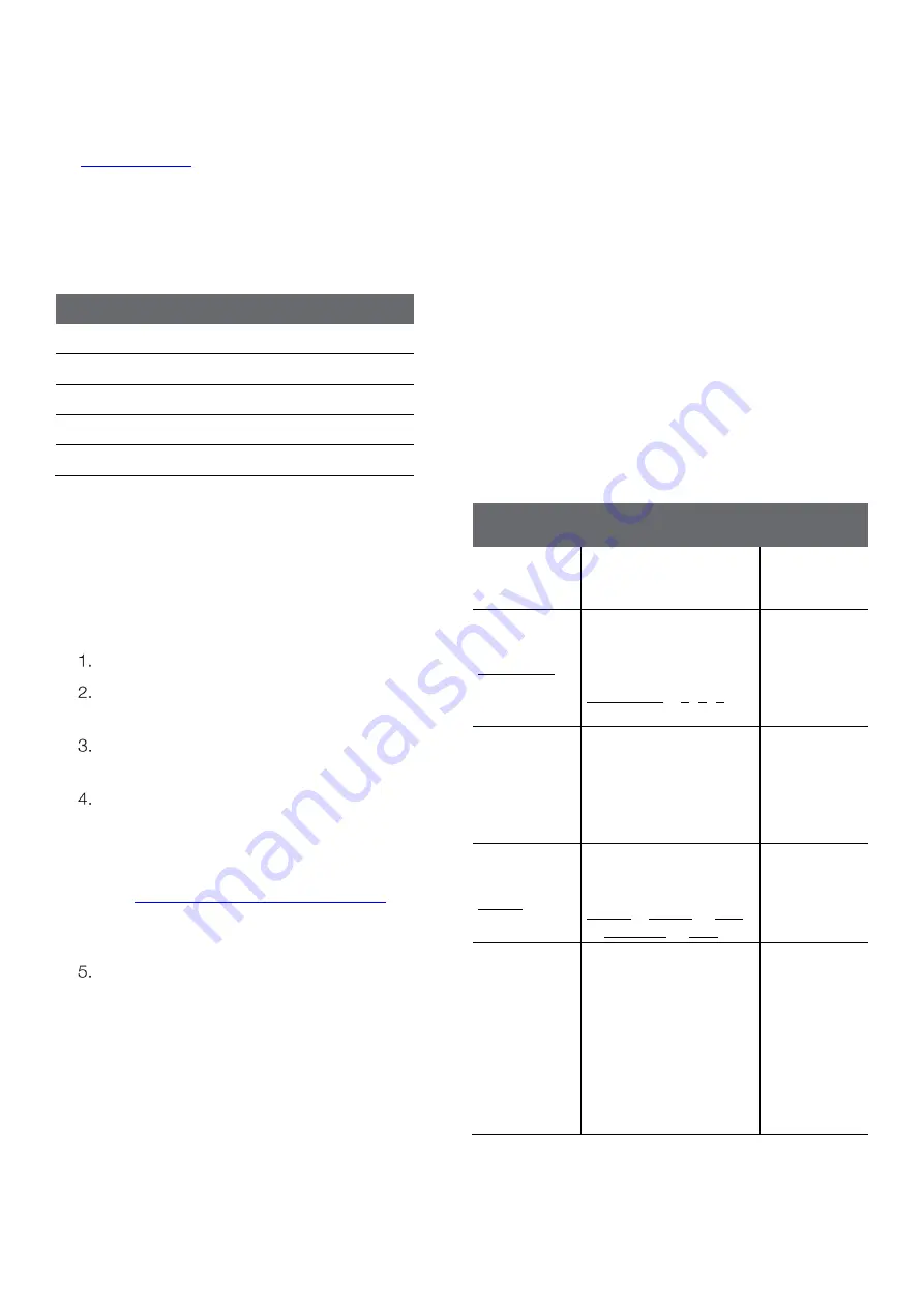
5.7.2 Remote Commands 

Remote commands allow the meter to be interfaced with 
computer software like LIMs and HyperTerminal.  

The remote engine receives input from the serial port and 
processes it. Commands sent to the remote interface will 
be in the form of “OPCODE <OPERAND> CR”.  


Only one command can be executed at a time. A 
new command cannot be issued until the previous 
command is done and prompt is given, shown as 
the greater than symbol (“>”) followed by a space. 


Empty commands (i.e. just a <CR>) will be ignored 
and a new prompt will be issued.  


<CR> (Carriage Return, ASCII 13) is used to 
terminate a command. Whenever this character is 
received, the internal buffer will be processed. 


Remote commands are not case sensitive.  

Remote 

Command 

Action 

Example 

Command 

GETMEAS 
<CR> 

Prints the current 

measurement 

immediately 


GETMEAS 
Data Count 

<CR> 

Prints the current 

measurement for a set 
number of times 


Data Count = 1, 2, 3, 
etc. 

GETMEAS 2 

GETCAL 
<CR> 

Prints all current 
calibration data 

 
If no calibration is saved, 

returns “>” to receive 

next command 


GETCAL 
MODE <CR> 

Prints the calibration 

data for specific mode 
 

MODE = COND or SAL 

or SAL PSU or TDS 

GETCAL 
COND 

GETLOG 

<CR> 

Prints all logged 

measurement data 
 

Output format is based 
on the Log Export Type 

setting 
 
If no data is logged, 
returns “>” to receive 
next command  


Summary of Contents for Orion Lab Star EC112

Page 1: ...Operations Manual Electrochemistry Meters 68X002223 Revision 01 June 2022 Orion Lab Star EC112 Conductivity Meter User Manual...

Page 2: ......

Page 3: ...u Value Changes 9 2 3 3 Mode Shortcut Key 9 2 3 4 Date and Time View Shortcut Key 9 2 4 Display Overview 10 2 5 Meter Connections 11 2 6 Electrode Information 11 2 7 Meter Startup Sequence 11 Chapter...

Page 4: ...24 Chapter 4 25 Calibration 25 4 1 Conductivity Calibration 25 4 1 1 Calibration Overview 25 4 1 2 Conductivity Calibration Procedure 26 4 1 3 Conductivity Calibration Example 26 4 1 4 Conductivity Va...

Page 5: ...fications 35 7 2 Meter Dimensions 36 7 3 Warranty 36 7 3 1 Return of Items 36 Chapter 8 37 Regulatory Compliance 37 8 1 European Union 37 8 2 Product Safety 37 8 3 Electromagnetic Compatibility 37 8 3...

Page 6: ...d result in minor to moderate injury or damage to the equipment Note This symbol in the context of a Note indicates to follow the manufacturer specified instructions notes and requirements set out in...

Page 7: ...on a clean dry surface Identify the side of the meter that the holder will be installed on and remove the screw between the circles on that side of the meter Align the base plate of the holder with th...

Page 8: ...ack the power supply provided with the meter Select the appropriate wall plug plate for the power outlet that will be used Slide the appropriate wall plug plate into the groove on the back of the powe...

Page 9: ...up Menu Press to accept a calibration point in the Calibration mode Press to power on the meter When the meter is on press to turn the backlight off or on When the meter is on press and hold for three...

Page 10: ...y Icon Indicates meter is in the Setup Menu and viewing the data log or calibration log Log Saved Icon Indicates meter is actively saving data to the data log or calibration log Continuous Icon Indica...

Page 11: ...ns for specific care and maintenance procedures The following are general recommendations for electrode preparation Remove the packaging from the electrode and save for storage Rinse the electrode usi...

Page 12: ...mperature Input When conductivity electrode with built in ATC sensor is connected use the Temp Calibration menu to perform a temperature offset calibration When conductivity electrode without ATC sens...

Page 13: ...ta and calibration log options Press key Press key Press key Press key Press key Press the Enter key to view the display log 3 2 1a Viewing the Data Log Press the Enter key to view the display log For...

Page 14: ...to view the display log For the calibration log press the or key to change the view from the date time screen to the calibration data screen Press or key For the calibration log press the or key to sc...

Page 15: ...off Press the Enter key to save the change 3 2 3 Export All Logs Send all saved data logs and calibration logs to the selected export device Note that this menu will not be shown if the Log Export Typ...

Page 16: ...he temperature offset value will be shown in the 2nd field a Press the key to increase the value by 0 1 Press and hold the key to quickly increase b Press the key to decrease the value by 0 1 Press an...

Page 17: ...ce reading Once a calibration is performed the entered nominal cell constant K multiplied by the calculated calibration factor is used to determine conductivity salinity and TDS measurement values fro...

Page 18: ...tup Menu list until the Temperature Compensation Coefficient item is shown Press the or key to set the coefficient value a Press the key to increase the value by 0 01 Press and hold the key to quickly...

Page 19: ...ly updated on the display and the stopwatch stabilizing or checkmark stable icon indicates the measurement stability status Press the Log Export key to save a measurement to the data log and export Au...

Page 20: ...me value by one second Press and hold the key to quickly decrease Press the Enter key to save the change 3 2 12 Calibration Due Alarm Set the calibration due alarm interval from 0 hours off to 168 hou...

Page 21: ...mperature Units item is shown Press the or key to set the temperature units Press the Enter key to save the change 3 2 14 Set Date Format Set the date format as month day year MM DD YYYY or day month...

Page 22: ...lash Press the or key to adjust the year a Press the key to increase by one year Press and hold the key to quickly increase b Press the key to decrease by one year Press and hold the key to quickly de...

Page 23: ...nter key to save the change 3 2 18 Sleep Mode Set the sleep mode on or off When the meter sleep mode is on the meter will enter sleep mode when no keys are pressed for 20 minutes Once the meter is in...

Page 24: ...erased The meter will confirm when the selected log is fully erased The meter will return to the measurement screen 3 2 20 Factory Reset Erase all data logs calibration logs and settings and return th...

Page 25: ...25 C The Temperature Compensation Coefficient setting in the Setup Menu will determine how the conductivity calibration standards are displayed during the calibration If temperature compensation is se...

Page 26: ...Proceed to the next calibration point or save and end the calibration a To proceed to the next calibration point repeat steps 3 5 or b To save and end the calibration press the Cal key The meter will...

Page 27: ...value is shown and then the Calibration Done screen is shown The meter will proceed to the main measure mode 4 1 4 Conductivity Value vs Temperature The following table lists theoretical values for t...

Page 28: ...4 3 TDS Calibration Ensure the active measure mode is TDS Press the Cal key to start the calibration Rinse the conductivity electrode and place into the TDS standard Wait for the TDS value to stabili...

Page 29: ...temperature and NIST traceable thermometer Press the Menu key to enter the Setup Menu Press the or key to scroll through the Setup Menu list until the Temp Calibration item is shown The temperature v...

Page 30: ...e entire time the meter is in the measurement mode 5 2 Conductivity Salinity and TDS Measurements Rinse the electrode with distilled water or appropriate solution and blot gently with a lint free tiss...

Page 31: ...erature meter Both the Actual TDS and the Actual Conductivity values must be in the same magnitude of units For example if the TDS value is in ppm the conductivity value must be in S cm if the TDS val...

Page 32: ...er using computer programs such as LIMs Putty LabView HyperTerminal or similar programs a To record the COM port location of the computer cable use the computer s Device Manager tool 5 7 2 Remote Comm...

Page 33: ...rograms and Features tool Make sure the meter is interfaced with the computer using the USB computer cable and the driver has been installed according to the instructions in the USB Computer Cable Int...

Page 34: ...the sample solution with the electrode sensing plates and temperature sensor submerged below the top of the sample solution o Verify cables do not have any damage o Perform a factor reset on the mete...

Page 35: ...oint Offset adjustment Up to 5 C Features Display 5 backlit LCD Time and date Yes Time format 12 hour AM PM or 24 hour Read types Continuous Auto Read Timed Timed interval 5 seconds to 60 minutes Data...

Page 36: ...d on a charged basis The warranty on your meter shall not apply to defects resulting from Improper or inadequate maintenance by customer Unauthorized modification or misuse Operation outside of the en...

Page 37: ...environment This equipment generates uses and can radiate radio frequency energy and if not installed and used in accordance with the instruction manual may cause harmful interference to radio commun...

Page 38: ...der entsorgt werden Mehr Informationen ber die Einhaltung dieser Anweisungen durch Thermo Scientific dieVerwerter und Hinweise die Ihnen n tzlich sein k nnen die Thermo Fisher Scientific Produkte zu i...

Page 39: ...TARA 109 9 2 Electrode and Solution Ordering Info Description Catalog Number Orion conductivity ATC electrode 2 cell K 1 0 epoxy platinum 1 5m cable 011050MD Orion conductivity ATC electrode 2 cell K...

Page 40: ...ety today Whether online in the plant in the field or in the lab scientists trust Orion products deliver precise and accurate readings which help you keep our communities healthier cleaner and safer F...

Reviews: