


2 | Safety Considerations
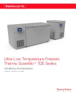
Thermo Fisher Scientific ULT Freezers
Safety Considerations
In this manual, the following symbols and conventions are
used:
Below are symbols and safety warnings that may be used on
the product: (see list on pages 5 & 6)
Below are important safety precautions that apply to this
product:
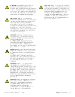
This symbol used alone indicates important
operating instructions which reduce the risk of
injury or poor performance of the unit.
CAUTION:
This symbol, in the context of a
CAUTION, indicates a potentially hazardous
situation which if not avoided could result in
minor to moderate injury or damage to the
equipment.
WARNING:
This symbol indicates potentially
hazardous situations which, if not avoided, could
result in serious injury or death.
WARNING:
This symbol indicates situations
where dangerous voltages exist and potential for
electrical shock is present.
The snowflake symbol indicates extreme low
temperatures and high risk of frostbite. Do not
touch bare metal or samples with unprotected
body parts.
This symbol indicates a need to use gloves during
the indicated procedures. If performing
decontamination procedures, use chemically
resistant gloves. Use insulated gloves for handling
samples and when using liquid nitrogen.
Before installing, using or maintaining this
product, please be sure to read this manual and
product warning labels carefully. Failure to follow
these instructions may cause this product to
malfunction, which could result in injury or
damage.
Use this product only in the way described in the
product literature and in this manual. Before using
it, verify that this product is suitable for its
intended use. If this equipment is used in a
manner not specified by the manufacturer, the
protection provided by the equipment may be
impaired.
Do not modify system components, especially
the controller. Use OEM exact replacement
equipment or parts. Before use, confirm that the
product has not been altered in any way.
WARNING:
Your unit must be properly grounded
in conformity with national and local electrical
codes. Never connect the unit to overloaded
power sources.
WARNING:
Disconnect the unit from all power
sources before cleaning, troubleshooting, or
performing other maintenance on the product or
its controls.
WARNING:
“Caution, risk of fire”. This unit is
charged with hydrocarbon refrigerants.
WARNING:
Ensure all ventilation openings are
not obstructed.
WARNING:
Do not use mechanical devices or
other means to accelerate the defrosting
process, other than those recommended by the
manufacturer.
WARNING:
Do not damage the refrigerant
circuit.
WARNING:
In order to reduce flammability
HAZARDS the installation of this equipment shall
only be carried out by a suitably qualified person.
WARNING:
Use of this equipment adjacent to or
stacked with other equipment should be avoided
because it could result in improper operation. If
such use is necessary, this equipment and the
other equipment should be observed to verify
that they are operating normally.
WARNING:
Use of accessories, transducers and
cables other than those specified or provided by
the manufacturer of this equipment could result in
increased electromagnetic emissions or
decreased electromagnetic immunity of this
equipment and result in improper operation.


