9
9
9
IT IS NECESSARY THAT ALL VALVES, FITTINGS AND
PIPING CONNECTIONS USED ARE SOLAR RATED
AND ARE ABLE TO WITHSTAND TEMPERATURES OF
UP TO 220°C.
SYSTEM PLUMBING
SYSTEM LAYOUT
The system components that are a part of a typical
electric solar hot water systems are depicted in the
system schematic in Figure 5 in Appendix (page 15).
Refer to the schematic to get an understanding of how
the system should be set up.
See Table 2 below for the corresponding numbered
components to the schematic for electric systems.
Table 2 Components that make up a typical Electric Boosted Solar
hot water system.
NO.
COMPONENT
FUNCTION
4
Tank
Stores hot water for when you need it
5
PTRV
Pressure Temperature Relief Valve
6
Electric element
Provides a backup energy source for
cloudy days and legionella protection
BELOW ARE ADDITIONAL COMPONENTS REQUIRED TO
UPGRADE YOUR TANK TO A SOLAR HOT WATER SYSTEM
1
Evacuated tube
collector
Solar energy collection
2
Controller
Monitors temperatures and controls
the system
2
Circulation Pump
Circulates water from the tank to the
manifold
3
Tempering Valve
Tempers the hot water down to a safe
outlet temperature
PIPING
Pipe Material and Pipe Size:
For domestic installations, the recommended pipe is
copper and the size is ½”.
Two factors affect the choice of pipe sizing, the flow
rate and pressure drop. These two factors are closely
related; a higher pressure drop will reduce the flow rate.
Pressure drop increases with decreased pipe diameters
as well as the presence of bends, elbows and other
components that restrict flow.
It may be necessary for some installations with
numerous pipe bends and significant pipe runs to
increase the pipe diameter to reduce the pressure drop.
All pipe work must be installed in accordance with AS/
NZS 3500.4.
STORAGE TANK
Storage Tank Ports:
Thermann tanks are hot water storage tanks that
contain seven ports:
1. Inlet (Mains):
Inlet line from mains water supply
2. Solar Flow:
Flow line to the collector
3. Solar Return:
Return line from the collector
4. Outlet:
Outlet line to tempering valve and load
5. Sensor 1 Port:
Bottom temperature sensor
6. Sensor 2 Port:
Top temperature sensor
7. PTRV:
Pressure and temperature relief valve
location
Two brass plugs are provided with the EHW Tank, these
can be used to plug the solar flow and return ports
while they are not being used in a solar DHW system
set up.
Outlet:
The outlet is where the hot water from the tank is
extracted to be supplied to the household.
Sensor Ports:
When solar DHW system is set up, the sensors must be
coated with heat transfer paste and inserted through
the cable gland into the appropriate sensor port and
tightened. The top sensor port houses S3 and the
bottom sensor port houses S2.
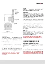
The Thermann controller requires three sensor leads be
installed into the appropriate sensor ports in the solar
system; this is vital for operation of the solar system.
The first temperature sensor port is located on either
side of the collector manifold. Sensor 1 (S1) must be
connected to the outlet of the manifold (the higher
side). Thermann solar rated tanks come with two
temperature sensor ports. The bottom port connects to
the Sensor 2 (S2), the top port connects to the Sensor
3 (S3) sensor.
9
9
9
IT IS NECESSARY THAT ALL VALVES, FITTINGS AND
PIPING CONNECTIONS USED ARE SOLAR RATED
AND ARE ABLE TO WITHSTAND TEMPERATURES OF
UP TO 220°C.
SYSTEM PLUMBING
SYSTEM LAYOUT
The system components that are a part of a typical
electric solar hot water systems are depicted in the
system schematic in Figure 5 in Appendix (page 15).
Refer to the schematic to get an understanding of how
the system should be set up.
See Table 2 below for the corresponding numbered
components to the schematic for electric systems.
Table 2 Components that make up a typical Electric Boosted Solar
hot water system.
NO.
COMPONENT
FUNCTION
4
Tank
Stores hot water for when you need it
5
PTRV
Pressure Temperature Relief Valve
6
Electric element
Provides a backup energy source for
cloudy days and legionella protection
BELOW ARE ADDITIONAL COMPONENTS REQUIRED TO
UPGRADE YOUR TANK TO A SOLAR HOT WATER SYSTEM
1
Evacuated tube
collector
Solar energy collection
2
Controller
Monitors temperatures and controls
the system
2
Circulation Pump
Circulates water from the tank to the
manifold
3
Tempering Valve
Tempers the hot water down to a safe
outlet temperature
PIPING
Pipe Material and Pipe Size:
For domestic installations, the recommended pipe is
copper and the size is ½”.
Two factors affect the choice of pipe sizing, the flow
rate and pressure drop. These two factors are closely
related; a higher pressure drop will reduce the flow rate.
Pressure drop increases with decreased pipe diameters
as well as the presence of bends, elbows and other
components that restrict flow.
It may be necessary for some installations with
numerous pipe bends and significant pipe runs to
increase the pipe diameter to reduce the pressure drop.
All pipe work must be installed in accordance with AS/
NZS 3500.4.
STORAGE TANK
Storage Tank Ports:
Thermann tanks are hot water storage tanks that
contain seven ports:
1. Inlet (Mains):
Inlet line from mains water supply
2. Solar Flow:
Flow line to the collector
3. Solar Return:
Return line from the collector
4. Outlet:
Outlet line to tempering valve and load
5. Sensor 1 Port:
Bottom temperature sensor
6. Sensor 2 Port:
Top temperature sensor
7. PTRV:
Pressure and temperature relief valve
location
Two brass plugs are provided with the EHW Tank, these
can be used to plug the solar flow and return ports
while they are not being used in a solar DHW system
set up.
Outlet:
The outlet is where the hot water from the tank is
extracted to be supplied to the household.
Sensor Ports:
When solar DHW system is set up, the sensors must be
coated with heat transfer paste and inserted through
the cable gland into the appropriate sensor port and
tightened. The top sensor port houses S3 and the
bottom sensor port houses S2.
The Thermann controller requires three sensor leads be
installed into the appropriate sensor ports in the solar
system; this is vital for operation of the solar system.
The first temperature sensor port is located on either
side of the collector manifold. Sensor 1 (S1) must be
connected to the outlet of the manifold (the higher
side). Thermann solar rated tanks come with two
temperature sensor ports. The bottom port connects to
the Sensor 2 (S2), the top port connects to the Sensor
3 (S3) sensor.


