background image


                                     1                                                          Rev.2  07/26/98 

HALOGUARD

TM

 II/IR 

MULTI-GAS MULTI-SENSOR MONITOR 

INSTRUCTION MANUAL  


SE R IA L  N O .

M O D E L  N O .

Tem p. R ange

1 - = > 60

o

F

2 - = 40 - 60

o

F

3 - = < 40

o

F        

N o. of Sensors/G as Type


   A  - R -11

   B  - R -12
   C  - R -22 


O utputs

   D  - R -134a

1 - 4 x 3A  R elays

   E   - R -113

2 - 4 x 0 - 5 V D C

   F -  N H

3


or 0 - 10 V D C

   G  - R -123

   H  - O xygen


O ptions/A ccessories

  A  - A udible A larm
  B  -  U PS

  C  - A uto C alibration
  E - Inlet/Exhaust Extension

  L - Strobe Light
  T - TW A  Integration


11285 Elkins Road Bldg. H-1 

Roswell, GA 30077 

TEL:  770-667-3865 

FAX: 770-667-3857 

www.thermalgas.com 

Distributed by:

Air-Met Scientific Pty Ltd

Work with Confidence

Air-Met Sales/Service


P: 1800 000 744 

F: 1800 000 774 

E: [email protected]

Air-Met Rental


P: 1300 137 067 

E: [email protected] 

W: www.airmet.com.au

Summary of Contents for HALOGUARD II/IR

Page 1: ...r 0 10 VDC G R 123 H Oxygen Options Accessories A Audible Alarm B UPS C Auto Calibration E Inlet Exhaust Extension L Strobe Light T TW A Integration 11285 Elkins Road Bldg H 1 Roswell GA 30077 TEL 770...

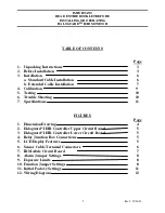
Page 2: ...Calibration 9 5 Testing 10 6 Trouble Shooting 10 7 Specifications 11 FIGURES Page 1 Dimension Drawing 4 2 Haloguard II IR Controller Upper Circuit Board 5 3 Haloguard II IR Controller Lower Circuit B...

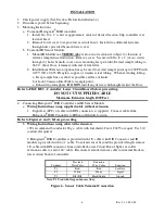
Page 3: ...urce of 115 230 VAC 50 60 Hz single phase circuit rated 15A minimum for both Haloguard II IR Controller and IR Sensor Module b IR Sensor Module should be mounted near potential leaks in a quiet area o...

Page 4: ...scale c OFFSCALE LED and Relay Factory set at 1000ppm See Figure 11 d HI Alarm LED LO Alarm LED and Relays User adjustable 10ppm to 1000ppm See Figure 8 Note Optional TWA Integration activates LOW Ala...

Page 5: ...ans Auto Scan Mode Gas Type R 11 R 12 R 123 R 134 O2 etc Sensor Type CMOS Halocarbon NH3 Infrared Halocarbons Chemical O2 Alarm Messages LO ALARM TWA ALARM HI ALARM OFFSCALE FAULT Figure 5 LCD Display...

Page 6: ...tmosphere DO NOT install any device which might restrict the flow Refer to FIGURE 3 Controller Lower Circuit Board before proceeding DO NOT CUT SUPPLIED CABLE Maximum Extension length 1000 Feet 4 Conn...

Page 7: ...l Adjust potentiometer to the left of each screw terminal with screwdriver until it reads 4 975 VDC THIS SET UP MUST BE COMPLETED FOR EACH IR MODULE 1 thru 6 Sequence to subsequent active channels usi...

Page 8: ...on Upper Circuit Board Figure 2 Select required settings from the following menu JP HALOGUARD II IR CONTROLLER FUNCTIONS JP 1 In house ONLY JP 2 Optional Autocalibration See 7a JP 3 Set scan rate 0 1...

Page 9: ...s corrected f Audible Alarm Jumper on JP 9 is factory installed to activate alarm circuit To disable alarm remove JP 9 jumper WARNING ANALOG OUTPUT IS A DRIVEN SIGNAL DO NOT CONNECT ANY WIRE WITH VOLT...

Page 10: ...ayed PPM value drops then Haloguard II IR is detecting the gas of interest or a gas that absorbs IR light at the same frequency LCD should display 0 ppm If LCD does not show 0 ppm follow calibration p...

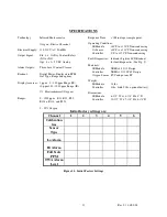
Page 11: ...se Time 1 Minute per sample point Operating Conditions IR Module 40o F to 120o F Non condensing O2 Sensor 40o F to 110o F Non condensing Controller 0o F to 120o F Non condensing Fault Diagnostics Indi...

Reviews: