


3-1
User Manual PN 84469 Rev L
GETTING STARTED
GETTING STARTED
STEP 1: Connect Phone (standard POTS handset) or Ethernet VoIP Phone to BDU.
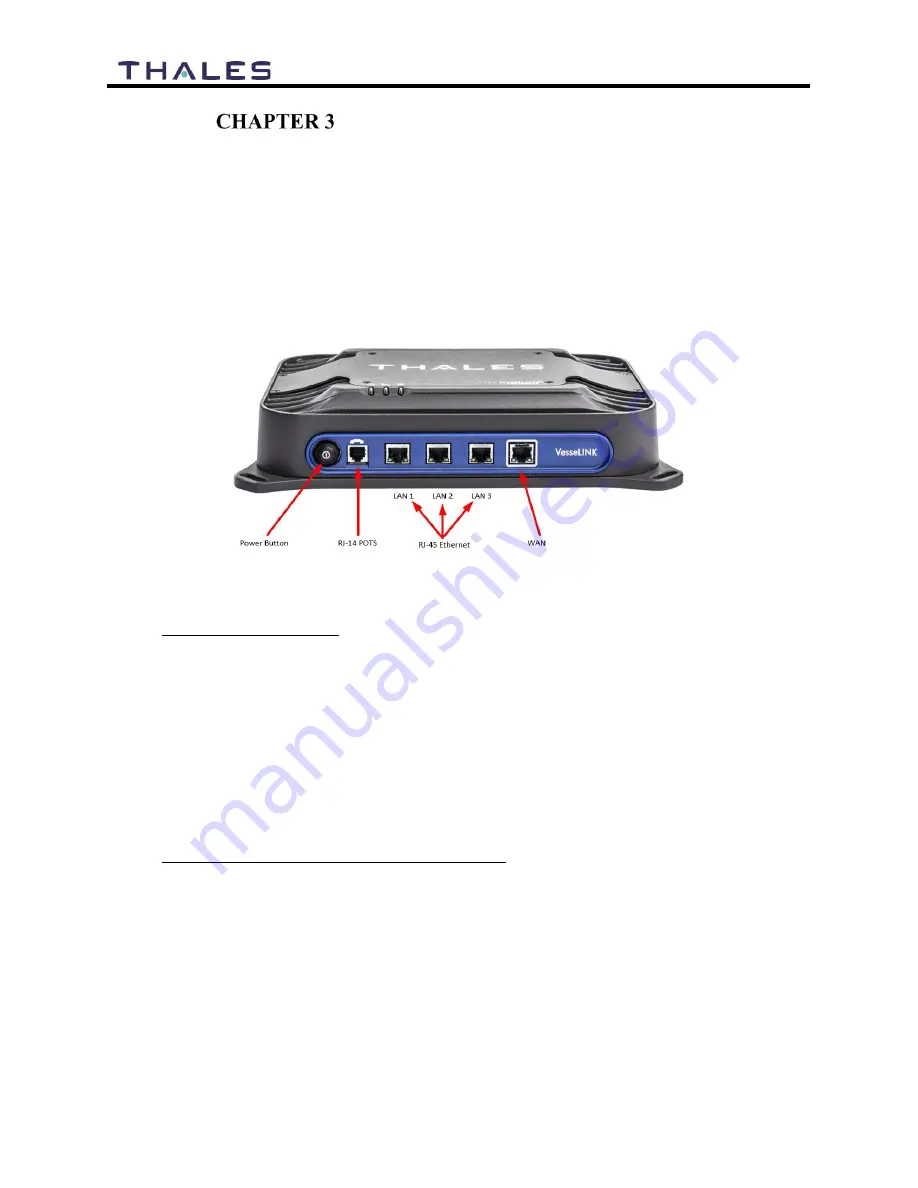
The BDU front has a main power button, one RJ-14 connector for POTS (Plain Old
Telephone Service), three PoE (Power over Ethernet) RJ-45 connectors for VoIP phones
or Computers, and one WAN (Wide Area Network) connector. Refer to Figure 3-1 for
location of the connectors.
Figure 3-1 BDU Front Panel Detail
POTS Phone connection
By default, the POTS Phone(s) are pre-configured to use the first two Iridium voice lines
without any additional configuration.
The BDU can accept up to two (2) POTS Phones connected with a RJ-14 Splitter (not
provided). Using a RJ-14 Splitter, the two POTS phones can each have a separate phone
line (not two phones using the same phone line). Note that single, molded plastic piece
RJ-14 Splitters (triplex jacks) will not fit into the POTS phone connector. It is
recommended that a POTS Splitter be used that includes a short phone cord that fits into
the BDU POTS connector.
VoIP or Thales SureLINK IP Phone connection
By default the BDU has three (3) extensions preconfigured for use with POTS phones,
VoIP phones, or the Thales SureLINK IP Handsets as shown in Table 3-1.
If using a VoIP phone, Thales recommends CISCO SPA504G and Grand Stream
GXP2140 models for use with VesseLINK
™
. Other brands and models may be supported
but functionality cannot be guaranteed.
Follow your VoIP phone configuration guide to setup the VoIP phone and connect to the
BDU using the following parameters. For detailed VoIP phone setup see Chapter 4,
Summary of Contents for VesseLINK Certus 200
Page 12: ...xii Uer Manual PN 84469 Rev L ...
Page 13: ...xiii Uer Manual PN 84469 Rev L ...
Page 15: ...xv Uer Manual PN 84469 Rev L ...
Page 16: ...xvi Uer Manual PN 84469 Rev L ...
Page 17: ...xvii Uer Manual PN 84469 Rev L ...
Page 18: ...xviii Uer Manual PN 84469 Rev L ...
Page 28: ...2 8 User Manual PN 84469 Rev L THIS PAGE INTENTIONALLY LEFT BLANK ...
Page 58: ...4 22 User Manual PN 84469 Rev L Figure 4 25 Settings Wi Fi Screen ...
Page 62: ...4 26 User Manual PN 84469 Rev L Figure 4 26 Settings LAN Screen ...
Page 65: ...4 29 User Manual PN 84469 Rev L Figure 4 27 Settings WAN Screen ...
Page 68: ...4 32 User Manual PN 84469 Rev L Figure 4 28 Settings Phone Screen ...
Page 78: ...4 42 User Manual PN 84469 Rev L Figure 4 35 Settings Radio Gateway ...
Page 84: ...4 48 User Manual PN 84469 Rev L Figure 4 37 Settings Secondary Data Flows ...


