background image

  FMS GENERAL DESCRIPTION 

14  FMGS OPERATION 


Lateral guidance 
 
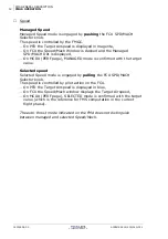
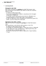
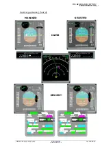
Managed mode: NAV 
NAV mode is engaged by pushing the HDG/TRK Selector knob. 
Lateral guidance is controlled by the FMGC to follow the trajectory 
defined in FMS. 

− 

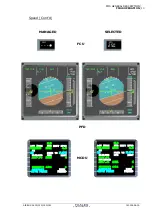
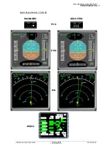
On PFD the FMA displays NAV, 

− 

On FCU the Heading/Track Window is dashed and the Managed 
Lateral Dot is displayed, 

− 

On PFD/ND actual heading and actual track are displayed, but 
selected Heading or Track Index (blue) is not displayed, 

− 

On ND the flight plan track is displayed by a continuous green line, 

− 

MCDU is used to change the flight path. 

 
Selected mode: HDG (or TRK) 
HDG (or TRK) mode is engaged by pulling the HDG/TRK Selector 
knob. 
Lateral guidance is controlled by pilot selection on the FCU.  

− 

On PFD the FMA displays HDG (or TRK), 

− 

On PFD/ND the selected Heading or Track Index (blue) is displayed, 

− 

On ND flight plan track is displayed by a dashed green line, and 
actual track by a continuous green line, 

− 

On FCU the Heading/Track Window displays the Target Heading 
(Track). 


J43126AA 00 


© THALES AVIONICS S.A. 

AIRBUS A318/319/320/321 


Summary of Contents for FMGS

Page 1: ...New FM Pilot s Guide New FM Pilot s Guide REV 1 REV 1 A318 A319 A320 A321 A318 A319 A320 A321 Aerospace Division ...

Page 2: ......

Page 3: ...ons 3 List of Effective Pages 3 1 4 CONVENTIONS USED IN THE GUIDE 3 Page identification 3 Text format 5 Figures 5 Cautions 5 Pilot s actions 5 Supplementary information 6 Terminology 6 2 RECORD OF REVISIONS 1 3 LIST OF EFFECTIVE PAGES 1 FOREWORD 1 PART I GENERAL DESCRIPTION 2 PART II FLIGHT PHASE PROCEDURES 3 PART III MULTI PHASE PROCEDURES 8 PART IV DEGRADED OPERATIONS 14 PART V APPENDICES 15 AIR...

Page 4: ...FOREWORD 2 CONTENTS PAGE INTENTIONALLY LEFT BLANK J43126AA 00 THALES AVIONICS S A AIRBUS A318 319 320 321 ...

Page 5: ...lot s Guide or part thereof by any means Whilst every effort has been made to ensure the high quality and accuracy of the information enclosed THALES AVIONICS MAKES NO WARRANTY EXPRESS OR IMPLIED CONCERNING THIS PILOT S GUIDE AND THE CONTENT THEREOF THALES AVIONICS EXPRESSLY DISCLAIMS ALL WARRANTIES INCLUDING BUT NOT LIMITED TO WARRANTIES OF ACCURACY COMPLETENESS OR FITNESS FOR A PARTICULAR OR INT...

Page 6: ...ional copies to be notified of further revisions PLEASE CONTACT techpubs frontoffice fr thalesgroup com Technical Publications Department 18 Avenue du Maréchal Juin B P 49 92362 Meudon la Forêt Cedex France Tel 33 1 39 45 50 00 Fax 33 1 39 45 58 71 J43126AA 00 THALES AVIONICS S A AIRBUS A318 319 320 321 ...

Page 7: ...written by pilots for pilots It provides information on utilization of the Flight Management FM functions of the FMGS It is primarily intended for system familiarization during the initial phases of training on type and as a reference aid during line operations It does not replace the AIRBUS approved procedures specified in the FCOM and OPERATORS manuals which take precedence AIRBUS A318 319 320 3...

Page 8: ...FOREWORD 4 DISCLAIMER PAGE INTENTIONALLY LEFT BLANK J43126AA 00 THALES AVIONICS S A AIRBUS A318 319 320 321 ...

Page 9: ...UND 9 DONE PART III MULTIPHASE FUNCTIONS 1 MCDU MENU page 2 F PLN pages 3 LATERAL F PLN management 4 VERTICAL F PLN management 5 SEC F PLN 6 FUEL monitoring 7 NAVIGATION management monitoring 8 ENGINE OUT OPERATION 9 DATA LINK 10 PRINT FUNCTION PART IV FMGS DEGRADED OPERATIONS 1 OVERVIEW 2 FMGC RESETS AND FAILURES 3 MCDU ANOMALIES 4 OTHER DEGRADED OPERATIONS PART V APPENDICES 1 MESSAGES 2 MCDU NAM...

Page 10: ... pilot s tasks during a normal flight from preflight through takeoff climb descent and approach to landing and go around Examples of data entered based on a sample flight scenario are given to assist clarity Part III MULTIPHASE FUNCTIONS is a description of FM operations which can be performed in the same way during different flight phases Part IV DEGRADED OPERATION is a description of FM operatio...

Page 11: ...rrect approval date the user has to apply for replacements Record of Revisions The Record of Revisions contains revision date short description and additional columns for date inserted and incorporator s initials Revisions are issued on the assumption that previous revisions have been incorporated List of Effective Pages The List of Effective Pages enables the user to determine that the manual is ...

Page 12: ...FOREWORD 4 STRUCTURE OF GUIDE A normal blank page within a page block is identified with the phrase INTENTIONALLY LEFT BLANK J43126AA 00 THALES AVIONICS S A AIRBUS A318 319 320 321 ...

Page 13: ... of a control or display element and an action verb These actions are written using bold font The possible pilot s actions are ACTION Description and example Enter means keying in information in MCDU scratchpad then pressing the specified LSK to insert this entry into the required data field Ex COST INDEX 5L Enter This Action allows to enter the cost index written in the scratchpad by pressing the...

Page 14: ...knob on FCU to obtain managed guidance Ex FCU ALT Select Push Supplementary information Details not essential for operational use are omitted Additional information which may be of interest is provided in italic text Terminology Technical terms appearing through the guide are listed in the Abbreviations in Appendices J43126AA 00 THALES AVIONICS S A AIRBUS A318 319 320 321 ...

Page 15: ...FOREWORD REVISIONS 1 2 RECORD OF REVISIONS Revision Reference Description Date inserted Initials J43126AA 00 First release DEC 2004 AIRBUS A318 319 320 321 THALES AVIONICS S A J43126AA 00 ...

Page 16: ...FOREWORD 2 REVISIONS PAGE INTENTIONALLY LEFT BLANK J43126AA 00 THALES AVIONICS S A AIRBUS A318 319 320 321 ...

Page 17: ...VE PAGES LIST OF EFFECTIVE PAGES LIST OF EFFECTIVE PAGES LIST OF EFFECTIVE PAGES LIST OF EFFECTIVE PAGES LIST OF EFFECTIVE PAGES LIST OF EFFECTIVE PAGES LIST OF EFFECTIVE PAGES LIST OF EFFECTIVE PAGES LIST OF EFFECTIVE PAGES 1 2 1 2 3 4 5 6 7 8 1 2 1 2 3 4 5 6 7 8 9 10 11 12 13 14 15 16 17 18 J43126AA 00 J43126AA 00 J43126AA 00 J43126AA 00 J43126AA 00 J43126AA 00 J43126AA 00 J43126AA 00 J43126AA 0...

Page 18: ...N FMGS OPERATION FMGS OPERATION FMGS OPERATION MCDU MCDU MCDU MCDU MCDU MCDU MCDU MCDU MCDU 1 2 1 2 1 2 3 4 5 6 7 8 9 10 1 2 3 4 5 6 7 8 9 10 11 12 13 14 15 16 17 18 1 2 3 4 5 6 7 8 9 J43126AA 00 J43126AA 00 J43126AA 00 J43126AA 00 J43126AA 00 J43126AA 00 J43126AA 00 J43126AA 00 J43126AA 00 J43126AA 00 J43126AA 00 J43126AA 00 J43126AA 00 J43126AA 00 J43126AA 00 J43126AA 00 J43126AA 00 J43126AA 00 ...

Page 19: ...EFLIGHT PREFLIGHT PREFLIGHT PREFLIGHT PREFLIGHT PREFLIGHT PREFLIGHT PREFLIGHT PREFLIGHT PREFLIGHT PREFLIGHT PREFLIGHT PREFLIGHT PREFLIGHT PREFLIGHT PREFLIGHT PREFLIGHT PREFLIGHT PREFLIGHT PREFLIGHT PREFLIGHT 1 2 1 2 3 4 5 6 1 2 3 4 5 6 7 8 9 10 11 12 13 14 15 16 17 18 19 20 21 J43126AA 00 J43126AA 00 J43126AA 00 J43126AA 00 J43126AA 00 J43126AA 00 J43126AA 00 J43126AA 00 J43126AA 00 J43126AA 00 J4...

Page 20: ...30 31 32 33 34 35 36 37 38 39 40 41 42 43 44 45 46 1 2 3 4 5 6 7 8 9 10 1 2 3 4 5 6 7 8 9 10 11 J43126AA 00 J43126AA 00 J43126AA 00 J43126AA 00 J43126AA 00 J43126AA 00 J43126AA 00 J43126AA 00 J43126AA 00 J43126AA 00 J43126AA 00 J43126AA 00 J43126AA 00 J43126AA 00 J43126AA 00 J43126AA 00 J43126AA 00 J43126AA 00 J43126AA 00 J43126AA 00 J43126AA 00 J43126AA 00 J43126AA 00 J43126AA 00 J43126AA 00 J431...

Page 21: ...1 12 13 14 15 16 17 18 19 20 21 22 23 24 25 26 27 28 J43126AA 00 J43126AA 00 J43126AA 00 J43126AA 00 J43126AA 00 J43126AA 00 J43126AA 00 J43126AA 00 J43126AA 00 J43126AA 00 J43126AA 00 J43126AA 00 J43126AA 00 J43126AA 00 J43126AA 00 J43126AA 00 J43126AA 00 J43126AA 00 J43126AA 00 J43126AA 00 J43126AA 00 J43126AA 00 J43126AA 00 J43126AA 00 J43126AA 00 J43126AA 00 J43126AA 00 J43126AA 00 J43126AA 00...

Page 22: ...11 12 13 14 15 16 17 18 19 20 21 22 23 24 25 26 27 28 1 2 3 4 5 6 7 8 9 10 11 12 13 14 J43126AA 00 J43126AA 00 J43126AA 00 J43126AA 00 J43126AA 00 J43126AA 00 J43126AA 00 J43126AA 00 J43126AA 00 J43126AA 00 J43126AA 00 J43126AA 00 J43126AA 00 J43126AA 00 J43126AA 00 J43126AA 00 J43126AA 00 J43126AA 00 J43126AA 00 J43126AA 00 J43126AA 00 J43126AA 00 J43126AA 00 J43126AA 00 J43126AA 00 J43126AA 00 J...

Page 23: ... DONE PHASE DONE PHASE 15 16 17 18 19 20 21 22 23 24 25 26 27 28 29 30 1 2 3 4 5 6 7 8 9 10 11 12 13 14 1 2 3 4 5 6 7 8 J43126AA 00 J43126AA 00 J43126AA 00 J43126AA 00 J43126AA 00 J43126AA 00 J43126AA 00 J43126AA 00 J43126AA 00 J43126AA 00 J43126AA 00 J43126AA 00 J43126AA 00 J43126AA 00 J43126AA 00 J43126AA 00 J43126AA 00 J43126AA 00 J43126AA 00 J43126AA 00 J43126AA 00 J43126AA 00 J43126AA 00 J431...

Page 24: ... PLN management LATERAL F PLN management LATERAL F PLN management LATERAL F PLN management LATERAL F PLN management LATERAL F PLN management LATERAL F PLN management LATERAL F PLN management LATERAL F PLN management 1 2 1 2 3 4 5 6 1 2 3 4 5 6 7 8 9 10 11 12 13 14 1 2 3 4 5 6 7 8 9 10 11 12 13 14 15 16 17 18 19 20 J43126AA 00 J43126AA 00 J43126AA 00 J43126AA 00 J43126AA 00 J43126AA 00 J43126AA 00 ...

Page 25: ...ent LATERAL F PLN management LATERAL F PLN management LATERAL F PLN management LATERAL F PLN management LATERAL F PLN management LATERAL F PLN management LATERAL F PLN management LATERAL F PLN management LATERAL F PLN management LATERAL F PLN management LATERAL F PLN management LATERAL F PLN management LATERAL F PLN management LATERAL F PLN management 21 22 23 24 25 26 27 28 29 30 31 32 33 34 35 3...

Page 26: ...ment VERTICAL F PLN management VERTICAL F PLN management VERTICAL F PLN management VERTICAL F PLN management VERTICAL F PLN management VERTICAL F PLN management VERTICAL F PLN management VERTICAL F PLN management VERTICAL F PLN management VERTICAL F PLN management SEC F PLN SEC F PLN SEC F PLN SEC F PLN SEC F PLN SEC F PLN 69 70 71 72 1 2 3 4 5 6 7 8 9 10 11 12 13 14 15 16 17 18 19 20 21 22 23 24 ...

Page 27: ...ent monitoring NAVIGATION management monitoring NAVIGATION management monitoring NAVIGATION management monitoring NAVIGATION management monitoring NAVIGATION management monitoring NAVIGATION management monitoring NAVIGATION management monitoring NAVIGATION management monitoring NAVIGATION management monitoring NAVIGATION management monitoring NAVIGATION management monitoring 7 8 9 10 11 12 13 14 1...

Page 28: ...ON management monitoring NAVIGATION management monitoring ENGINE OUT ENGINE OUT ENGINE OUT ENGINE OUT ENGINE OUT ENGINE OUT ENGINE OUT ENGINE OUT ENGINE OUT ENGINE OUT ENGINE OUT ENGINE OUT DATA LINK DATA LINK DATA LINK DATA LINK DATA LINK DATA LINK DATA LINK DATA LINK DATA LINK DATA LINK 31 32 33 34 35 36 37 38 39 40 41 42 43 44 45 46 47 48 49 50 51 52 53 54 1 2 3 4 5 6 7 8 9 10 11 12 1 2 3 4 5 6...

Page 29: ...RINT FUNCTION PRINT FUNCTION 11 12 13 14 15 16 17 18 19 20 21 22 23 24 25 26 27 28 29 30 31 32 33 34 35 36 37 38 39 40 41 42 43 44 45 46 1 2 3 4 5 6 7 8 9 10 11 J43126AA 00 J43126AA 00 J43126AA 00 J43126AA 00 J43126AA 00 J43126AA 00 J43126AA 00 J43126AA 00 J43126AA 00 J43126AA 00 J43126AA 00 J43126AA 00 J43126AA 00 J43126AA 00 J43126AA 00 J43126AA 00 J43126AA 00 J43126AA 00 J43126AA 00 J43126AA 00...

Page 30: ...FAILURES FMGC RESETS AND FAILURES FMGC RESETS AND FAILURES FMGC RESETS AND FAILURES FMGC RESETS AND FAILURES FMGC RESETS AND FAILURES FMGC RESETS AND FAILURES FMGC RESETS AND FAILURES FMGC RESETS AND FAILURES FMGC RESETS AND FAILURES FMGC RESETS AND FAILURES FMGC RESETS AND FAILURES FMGC RESETS AND FAILURES FMGC RESETS AND FAILURES FMGC RESETS AND FAILURES FMGC RESETS AND FAILURES FMGC RESETS AND ...

Page 31: ...ESSAGES MESSAGES MESSAGES MESSAGES MESSAGES MESSAGES MESSAGES MESSAGES MESSAGES MESSAGES MESSAGES MESSAGES MESSAGES MESSAGES MESSAGES MESSAGES MESSAGES MESSAGES MCDU NAMING and DATA FORMAT MCDU NAMING and DATA FORMAT MCDU NAMING and DATA FORMAT MCDU NAMING and DATA FORMAT MCDU NAMING and DATA FORMAT 1 2 1 2 3 4 5 6 7 8 9 10 11 12 13 14 15 16 17 18 19 20 1 2 3 4 5 J43126AA 00 J43126AA 00 J43126AA 0...

Page 32: ... SUMMARY FMS RESETS SUMMARY OPC and AMI FILES OPC and AMI FILES OPC and AMI FILES OPC and AMI FILES OPC and AMI FILES OPC and AMI FILES ND SYMBOLS ND SYMBOLS ND SYMBOLS ND SYMBOLS ND SYMBOLS ND SYMBOLS ABBREVIATIONS ABBREVIATIONS ABBREVIATIONS ABBREVIATIONS ABBREVIATIONS 6 7 8 9 10 11 12 13 14 15 16 17 18 19 20 21 22 23 24 25 26 27 28 1 2 3 4 1 2 3 4 5 6 1 2 3 4 5 6 1 2 3 4 5 J43126AA 00 J43126AA ...

Page 33: ...S ABBREVIATIONS ABBREVIATIONS ABBREVIATIONS ABBREVIATIONS ABBREVIATIONS 6 7 8 9 10 11 12 J43126AA 00 J43126AA 00 J43126AA 00 J43126AA 00 J43126AA 00 J43126AA 00 J43126AA 00 PAGE REVISION MCDU FOLDOUT MCDU FOLDOUT 1 2 J43126AA 00 J43126AA 00 AIRBUS A318 319 320 321 THALES AVIONICS S A J43126AA 00 ...

Page 34: ...FOREWORD 18 LIST OF EFFECTIVE PAGES PAGE INTENTIONALLY LEFT BLANK J43126AA 00 THALES AVIONICS S A AIRBUS A318 319 320 321 ...

Page 35: ...AIRBUS A318 319 320 321 THALES AVIONICS S A J43126AA 00 Part I FMS GENERAL DESCRIPTION I II III IV IV V ...

Page 36: ...J43126AA 00 PAGE INTENTIONALLY LEFT BLANK THALES AVIONICS S A AIRBUS A318 319 320 321 ...

Page 37: ...3 2 2 SYSTEM INTERFACES 4 2 3 PILOT INTERFACES 5 2 4 FLIGHT PHASES 9 Chapter 3 FMGS OPERATION 3 1 FMS MODES OF OPERATION Dual Single Independent 3 3 2 TEMPORARY FLIGHT PLAN 6 3 3 NAVIGATION FLIGHT MANAGEMENT 7 3 4 SOFTWARE AND DATABASE 18 Chapter 4 MCDU 4 1 DESCRIPTION 3 4 2 GENERAL DISPLAY RULES 14 AIRBUS A318 319 320 321 THALES AVIONICS S A J43126AA 00 ...

Page 38: ...FMGS GENERAL PRESENTATION 2 CONTENTS PAGE INTENTIONALLY LEFT BLANK J43126AA 00 THALES AVIONICS S A AIRBUS A318 319 320 321 ...

Page 39: ...P Auto thrust A THR commands In addition the total system provides fault isolation and detection The FMGS consists of the following components 2 Flight Management Guidance Computers FMGC in avionics compartment 2 Multipurpose Control Display Units MCDU at sides of forward pedestal 1 Flight Control Unit FCU on glare shield 2 Flight Augmentation Computers FAC in avionics compartment Comprehensive na...

Page 40: ...FMS GENERAL DESCRIPTION 2 INTRODUCTION PAGE INTENTIONALLY LEFT BLANK J43126AA 00 THALES AVIONICS S A AIRBUS A318 319 320 321 ...

Page 41: ...PTION SYSTEM OVERVIEW 1 AIRBUS A318 319 320 321 THALES AVIONICS S A J43126AA 00 Part I Chapter 2 SYSTEM OVERVIEW Contents 2 1 FLIGHT DECK CONFIGURATION 3 2 2 SYSTEM INTERFACES 4 2 3 PILOT INTERFACES 5 2 4 FLIGHT PHASES 9 ...

Page 42: ...2 FMS GENERAL DESCRIPTION SYSTEM OVERVIEW J43126AA 00 THALES AVIONICS S A AIRBUS A318 319 320 321 PAGE INTENTIONALLY LEFT BLANK ...

Page 43: ...FMS GENERAL DESCRIPTION SYSTEM OVERVIEW 3 AIRBUS A318 319 320 321 THALES AVIONICS S A J43126AA 00 2 1 FLIGHT DECK CONFIGURATION The location of the cockpit components of the FMGS is shown below ...

Page 44: ...RVIEW J43126AA 00 THALES AVIONICS S A AIRBUS A318 319 320 321 2 2 SYSTEM INTERFACES The FMGCs receive and transmit signals from and to other aircraft systems Figure here under shows the interconnections between these systems and the FMGCs ...

Page 45: ...FMS GENERAL DESCRIPTION SYSTEM OVERVIEW 5 AIRBUS A318 319 320 321 THALES AVIONICS S A J43126AA 00 2 3 PILOT INTERFACES The figure shows the pilot interfaces and their interconnection ...

Page 46: ... AP FD A THR Selection of guidance modes Manual selection of flight parameters Layout of the FCU is shown below The MCDUs see Fold out at the end of the Guide are the long term strategic interface between crew and FMGC Main functions of the MCDUs include Insertion of initial position to align IRUs before flight Creation and display of Primary Secondary and Alternate flight plan Insertion of weight...

Page 47: ...ation of approach phase See Part 1 Ch 4 for detailed description of MCDU The Thrust Levers T L are also an interface for pilot inputs to the FMGCs and to the FADEC The Thrust Levers are shown below T L functions are Engagement of A THR and FD in take off mode thrust levers at FLX or DRT or TOGA position and engagement of A THR FD and or AP in go around mode T L at TOGA Selection of other thrust ra...

Page 48: ...The Flight Mode Annunciator FMA on the PFD indicates Armed or active status of the FMGS modes Engagement status of FD A P and A THR The FMA is the primary visual feedback of the FMGS operating modes to the crew Every mode change whether pilot selected or automatic should be verified by reference to the FMA Typical FMA indications are shown here under The PFD also displays FD or FPD commands and ta...

Page 49: ... or altitude speed constraints and computed TAS GS and wind Typical ND indications are shown here under 2 4 FLIGHT PHASES The flight phases of a typical FMS flight profile are shown in the Figure on the next page They are PREFLIGHT TAKEOFF CLIMB CRUISE DESCENT APPROACH GO AROUND DONE The switching conditions and procedures related to each phase are detailed in Parts II and III of this Guide The ac...

Page 50: ...10 FMS GENERAL DESCRIPTION SYSTEM OVERVIEW J43126AA 00 THALES AVIONICS S A AIRBUS A318 319 320 321 ...

Page 51: ...E Mode 5 INDEPENDENT Mode 5 3 2 TEMPORARY FLIGHT PLAN 6 3 3 NAVIGATION FLIGHT MANAGEMENT 7 Navigation 7 FMGC position 7 Radio navaids 9 Navigation information 10 In Flight Performance 10 Guidance modes 11 Speed 12 Lateral guidance 14 Vertical guidance 16 3 4 SOFTWARE AND DATABASE 18 AIRBUS A318 319 320 321 THALES AVIONICS S A J43126AA 00 ...

Page 52: ...FMS GENERAL DESCRIPTION 2 FMGS OPERATION PAGE INTENTIONALLY LEFT BLANK J43126AA 00 THALES AVIONICS S A AIRBUS A318 319 320 321 ...

Page 53: ...is associated with MCDU1 left pilot seat and FMGC2 with MCDU2 right pilot seat Throughout this manual the components may be referred to separately or collectively e g AP Autopilot A THR Auto thrust FD Flight Director FG Flight Guidance FM Flight Management FMS Flight Management System FMGC Flight Management and Guidance Computer FMGS Flight Management and Guidance System 3 1 FMS MODES OF OPERATION...

Page 54: ...n can be copied into the ACTIVE flight plan and vice versa The FMGCs are supplied by the aircraft electrical power The FMSs contain batteries which can maintain power supply and allow to keep entered data in the memory for at least 10 mn in the event of lost of normal electrical power supply The two FMGCs and their associated MCDUs operate together to cross check navigation accuracy and provide re...

Page 55: ...ion occurs automatically when one FMGC has failed the scratchpad amber message OPP FMGC IN PROCESS is displayed on the MCDU of the failed FMGC Entries on both MCDUs go to the operational FMGC See Part IV FMS Degraded Operation INDEPENDENT Mode The degraded Independent mode occurs automatically at power up if communication between the FMGCs is not possible or a mismatch between FMGCs is detected Th...

Page 56: ...fore inserting The FMS computes track profile and predictions of the Temporary Flight Plan according to the entered revisions This specific Thales feature enables the pilot to visualize revisions on the ND and thus avoid incorrect entries Because of this feature it is not necessary to insert the Temporary Flight Plan after each revision in turn which would waste time It is therefore recommended to...

Page 57: ...or Using GPS reference or Navaids reference when GPS is not available both FMGCs continuously monitor each IRS to determine and update an IRS error model This computation is done by a Kalman filter and provides a BEST position speed for each IRS The estimated IRS drift error is shown in the MCDU POSITION MONITOR page GPS provides an accurate position but may be affected by lack of satellite covera...

Page 58: ...position Criteria such distance figure of merit intersection angle are taken into account to select VOR DME VOR DME VORTAC TACAN ILS ILS DME LOC DME or LOC MLS When GPS and radio positions are not available the FMGCs use the triple mix IRS best position to determine through the filter the mixed best FMGC position POSITION MONITOR FMGC1 5019 0N 00130 8E 3IRS GPS FMCG2 5019 1N 00130 7E 3IRS GPS GPIR...

Page 59: ...MAX FL350 FL380 FL398 REPORT UPDATE AT BRG DIST TO PREDICTIVE GPS GPS PRIMARY REQUIRED ACCUR ESTIMATED 2 0NM HIGH 0 08NM 1 3IRS GPS LOC or MLS 2 3IRS GPS 3 3IRS DME LOC or MLS 4 3IRS VOR LOC or MLS 5 3IRS LOC or MLS More details are given in Part III POSITION MONITOR page and Part IV FMS Degraded Operation Radio navaids The FMS auto tunes the radio navaids contained in the Navigation Data Base to ...

Page 60: ...e and Tropopause aircraft parameters Idle Perf factors Step Altitude if applicable Speed and or altitude constraints can be inserted in the flight plan The FMS will manage the profile speed and or rate of climb descent to comply with the constraints In preflight phase the FMS uses the entered data to Compute optimum speed in each flight phase Provide predictions of time altitude passing top of cli...

Page 61: ...ght parameter selected directly by the pilot on the FCU Pilot action is to pull the appropriate mode selection knob then turn it to set the desired value of the parameter The aircraft can be operated with mixed selected and managed modes i e Lateral Guidance SELECTED and Speed MANAGED or Lateral Guidance MANAGED with Vertical Guidance SELECTED Vertical Guidance MANAGED mode is only available if La...

Page 62: ... target value Selected speed Selected Speed mode is engaged by pulling the FCU SPD MACH Selector knob The speed is controlled by pilot action on the FCU On PFD the Target Airspeed is displayed in blue On FCU the Speed Mach window displays the Target Airspeed On MCDU PERF page SELECTED mode is confirmed with the target value which is the reference for FMS computation in the current flight phase The...

Page 63: ...1541 4 3 CI 30 PRED TO FL070 MANAGED UTC DIST 250 79 1420 4 EXPEDITE 1420 2 ACTIVATE NEXT APPR PHASE PHASE CLB ACT MODE UTC DEST EFOB SELECTED 1544 4 3 CI 30 PRED TO FL070 MANAGED UTC DIST 250 79 SELECTED 250 40 1421 4 EXPEDITE 1421 2 ACTIVATE NEXT APPR PHASE PHASE MCDU AIRBUS A318 319 320 321 THALES AVIONICS S A J43126AA 00 ...

Page 64: ...ck Index blue is not displayed On ND the flight plan track is displayed by a continuous green line MCDU is used to change the flight path Selected mode HDG or TRK HDG or TRK mode is engaged by pulling the HDG TRK Selector knob Lateral guidance is controlled by pilot selection on the FCU On PFD the FMA displays HDG or TRK On PFD ND the selected Heading or Track Index blue is displayed On ND flight ...

Page 65: ...teral guidance Cont d MANAGED SELECTED J J J FCU PRM PFD ND THV001 UTC SPD ALT FISTO 1953 305 FL294 15 T C 1955 79 FL360 UN874 TRK399 69 FOUCO 2005 300 UN874 48 ADABI 2011 UN874 30NM BOKNO 2014 DEST UTC DIST EFOB EGLL27R 2100 502 4 5 MCDU THALES AVIONICS S A J43126AA 00 ...

Page 66: ...ESCENT V S or FPA OP CLB OP DES V S modes are engaged by pulling the Altitude Selector knob Vertical guidance is controlled by the pilot On PFD FMA displays OP CLB OP DES EXP CLB EXP DES as installed On FCU Altitude Window displays the target altitude the Managed Level Change white Dot is blank PFD Vertical deviation symbol Managed or Selected mode On PFD this symbol appears on the altitude scale ...

Page 67: ...398 REPORT VDEV 440 FT UPDATE AT BRG DIST 312 82 6 TO EGLL27L PREDICTIVE GPS GPS PRIMARY REQUIRED ACCUR ESTIMATED 2 0NM HIGH 0 08NM DESCENT THV001 CRZ OPT REC MAX FL398 REPORT VDEV 10 FT UPDATE AT BRG DIST 313 84 4 TO EGLL27L PREDICTIVE GPS GPS PRIMARY REQUIRED ACCUR ESTIMATED 2 0NM HIGH 0 08NM MANAGED SELECTED AIRBUS A318 319 320 321 THALES AVIONICS S A J43126AA 00 ...

Page 68: ...cy values printer options customized AOC options CO RTE retention Default speed below 10000 ft DIR TO default selection THR reduction and ACC heights All Eng Eng out Idle Perf factors Operational Program Configuration OPC The OPC file is a set of software programs pins Some options are chosen by the operator e g Weight Unit Length Unit 2nd ADF option GPS option AOC option Derated Take Off option D...

Page 69: ...L PRED key 8 SEC F PLN key 9 SLEW KEYS 9 ATC COMM key 10 MULTIPURPOSE key MCDU MENU key 10 AIRPORT key 10 ALPHANUMERIC keys 11 SPACE key 12 OVFLY key 12 CLR key 12 ON OFF AND BRIGHTNESS ADJUSTMENT keys 13 ANNUNCIATORS 13 4 2 GENERAL DISPLAY RULES 14 Non valid and Missing Data 14 Font size 14 Color code 15 Data Labels 16 Special symbols or displays 17 Data Entry 18 AIRBUS A318 319 320 321 THALES AV...

Page 70: ...FMS GENERAL DESCRIPTION 2 MCDU PAGE INTENTIONALLY LEFT BLANK J43126AA 00 THALES AVIONICS S A AIRBUS A318 319 320 321 ...

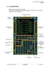
Page 71: ...he MCDU More details are given in later chapters TOP ANNUNCIATORS LINE SELECT KEYS FRONT ANNUNCIATOR ON OFF BRIGHTNESS ADJUSTMENT KEYS DISPLAY SCREEN LINE SELECT KEYS PAGE KEYS AIRPORT KEY SLEW KEYS ALPHA NUMERIC KEYS CLEAR KEY MULTI PURPOSE KEY ATSU KEY SPACE KEY OVERFLY KEY AIRBUS A318 319 320 321 THALES AVIONICS S A J43126AA 00 ...

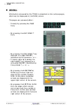
Page 72: ...s By pressing the LINE SELECT k adjacent to a page PROMPT identified by the symbols or ey In some cases by pressing the LINE SELECT key adjacent to a activation PROMPT identified by the symbols or By pressing the HORIZONTAL SLEW keys if more than one page for the specific function exist In this case horizontal arrows are displayed in the upper right corner of the screen By pressing the VERTICAL SL...

Page 73: ... The data lines are adjacent to the line select keys and the label line is just above the data line The bottom line line 14 is the scratchpad line and is used by the pilot to insert or modify data in the data fields or to display FMS messages LINE SELECT KEYS There are six line select keys LSK on each side of the display screen adjacent to the data lines The left keys are identified as 1L through ...

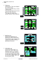
Page 74: ...T BRG DIST TO PREDICTIVE GPS GPS PRIMARY REQUIRED ACCUR ESTIMATED 1 00NM HIGH 0 08NM PERF key Pressing the PERF key displays the PERF page performance The PERF page provides performance data speeds and various vertical predictions associated with each flight phase CLB ACT MODE UTC DEST EFOB SELECTED 1933 4 1 CI 30 PRED TO FL070 MANAGED UTC DIST 250 79 SELECTED 250 40 1810 4 EXPEDITE 1810 2 ACTIVAT...

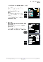
Page 75: ...__ _ TRIP TIME BLOCK __ _ RTE RSV 5 0 ALTN TIME TOW FINAL TIME LW 0030 EXTRA TIME DATA key Pressing the DATA key displays the DATA INDEX page 1 2 The horizontal slew keys access DATA INDEX page 2 2 These pages display sub menus from which other Data pages can be accessed DATA INDEX 1 2 POSITION MONITOR IRS MONITOR GPS MONITOR A C STATUS PRINT FUNCTION AOC FUNCTION DATA INDEX 2 2 PILOTS WAYPOINTS W...

Page 76: ...226 025 FIST4A 17NM ALIVA 6 8 275 032 DEST UTC DIST EFOB EGLL27R 2002 535 4 3 RADIO NAV VOR1 FREQ FREQ VOR2 TOU 117 70 117 70 TOU CRS CRS ILS FREQ CHAN MLS IRR 110 30 CRS SLOPE CRS F273 ADF1 FREQ FREQ ADF2 RAD NAV key Pressing the RAD NAV key displays the RADIO NAV page The RAD NAV page displays the navaids tuned by the FMS or selected by the pilot FUEL PRED AT UTC EFOB EGLL 2003 4 5 EHAM 2044 2 6...

Page 77: ...ociated pages wrap around from the last page to the first page and vice versa If a page contains more data than can fit on the display vertical arrows are displayed in the lower right corner of the display screen of the MCDU If both arrows and are displayed the displayed data can be scrolled either up or down Pushing the or key scrolls the display up or down that is to display the line below the c...

Page 78: ...The purpose of the AIRPORT key is to display the F PLN page which includes the next airport along the current flight plan All the functions and displays of the F PLN page are available on this page The first push of the Airport key following any other mode key displays the primary destination airport Successive pushes of the key show alternate destination if defined origin airport only before take...

Page 79: ...ent reversion from the LAT REV or VERT REV should return to this orientation when appropriate If a TMPY F PLN does not exist and a secondary page e g SEC INDEX SEC F PLN is not displayed pressing the AIRPORT key works on the active flight plan as described If a TMPY F PLN exists and a secondary page is not displayed pressing the AIRPORT key works on the temporary flight plan as described If a seco...

Page 80: ...clear key CLR is used to clear messages or data from the scratchpad or a data field Rules If pressed while the scratchpad is empty the CLR message is displayed To erase characters in the scratchpad A single short press of the clear key will erase the last character entered onto the scratchpad Pressing the clear key more than 2 seconds will erase the entire scratchpad To erase data from a data fiel...

Page 81: ...reen indicates that the MCDU has passed its long term power up or power off reset test after its BRIGHTNESS switch has been turned to OFF FM2 amber indicates FM2 failure Front annunciators M C D U M E N U F A I L F M FAIL amber is illuminated when the MCDU has failed FM white is illuminated when FM is not the active system and it has sent an important message Important messages are those displayed...

Page 82: ...ed in as the data becomes available Font size On the MCDU two sizes of font are used according to the following rules Large font to display all data on the data line line adjacent to LS key Small font to display data on the label line Data with default values or FM predicted values which could be changed by the pilot are displayed In small font when the FM supplied data are being used In large fon...

Page 83: ... Missed constraints Amber Constraints Max altitude Magenta ACTIVE F PLN Offset OFST in the title of F PLN Active HDG SEL or active TRK SEL Green waypoints white legs TMPY F PLN Yellow waypoints white legs SEC F PLN White waypoints white legs Missed approach Alternate Cyan waypoints white legs and associated with a prompt have the color of this prompt Slash when used to separate data fields are the...

Page 84: ...tion event Pseudo waypoints are speed limit SPD LIM top of climb T C top of descent T D top of step climb S C top of step descent S D deceleration point DECEL Flight plan markers Markers are displayed on the F PLN TMPY F PLN and SEC F PLN pages to mark either TMPY AEC001 UT210 UTC SPD ALT PERIG 1653 80 FL350 UY156 43 FOUCO 1659 F PLN DISCONTINUITY DIBAG 1700 80 UT210 45NM TUDRA 1706 TMPY TMPY ERAS...

Page 85: ...ot can press the key to activate the prompt or select some data At the upper right corner of the screen next previous page may be displayed with horizontal slew keys WPT WPT Horizontal arrows with WPT beside a fixed waypoint on the flight plan page indicates that the A C must turn at fixed waypoint in the indicated direction WPTU Triangle beside a fixed waypoint on the flight plan page indicates t...

Page 86: ...l can be entered with or without the leading FL When a data field contains two or more elements it can be entered one by one or as a single entry but separated by a slash If the first element is entered alone it does not need to be followed by a slash If the second element is entered alone it must be preceded by one or two slashes in order to be correctly identified by the FMS If the scratchpad co...

Page 87: ...AIRBUS A318 319 320 321 I II Part II FLIGHT PHASES PROCEDURES III IV V THALES AVIONICS S A J43126AA 00 ...

Page 88: ...J43126AA 00 PAGE INTENTIONALLY LEFT BLANK THALES AVIONICS S A AIRBUS A318 319 320 321 ...

Page 89: ...FROM STANDARD 7 3 4 OTHER INFORMATION 9 Chapter 4 CLIMB 4 1 SWITCHING CONDITIONS 3 4 2 NORMAL CLIMB 5 4 3 CONSTRAINTS MANAGEMENT 14 4 4 SUPPLEMENTARY PROCEDURES 18 4 5 USE OF PERF CLB PAGE 22 4 6 USE OF PROG CLIMB PAGE 26 4 7 SCRATCHPAD MESSAGES 28 Chapter 5 CRUISE 5 1 SWITCHING CONDITIONS 3 5 2 REACHING CRUISE FLIGHT LEVEL 4 5 3 NORMAL CRUISE 6 5 4 Use of PERF CRZ page 13 5 5 Use of PROG CRUISE p...

Page 90: ... CONDITIONS 3 7 2 BEFORE APPROACH ACTIVATION 5 7 3 APPROACH ACTIVATION 8 7 4 APPROACH MANAGEMENT 11 7 5 SUPPLEMENTARY PROCEDURES 26 Chapter 8 GO AROUND 8 1 SWITCHING CONDITIONS 3 8 2 Standard GO AROUND 4 8 3 RETURN for another approach 8 8 4 DIVERSION to ALTN Airport 10 Chapter 9 DONE 9 1 SWITCHING CONDITIONS 3 9 2 FLIGHT DECK INDICATIONS 3 9 3 SUPPLEMENTARY INFORMATION 5 9 4 Conditions for Switch...

Page 91: ...FLIGHT PHASES FLIGHT PLAN SCENARIO 1 Part II Chapter 1 FLIGHT PLAN SCENARIO Contents 1 1 ROUTE 3 1 2 FLIGHT PLAN DATA 4 AIRBUS A318 319 320 321 THALES AVIONICS S A J43126AA 00 ...

Page 92: ...FLIGHT PHASES 2 FLIGHT PLAN SCENARIO PAGE INTENTIONALLY LEFT BLANK J43126AA 00 THALES AVIONICS S A AIRBUS A318 319 320 321 ...

Page 93: ...LL LHR with alternate airport AMSTERDAM EHAM AMS is used in this guide as a support to describe the different flight phases E LFBO GLL EHAM UN874 UT191 UT426 UL620 REDFA BPK 6F BIG 3B DIMAL FISTO FOUCO BAMES ABUDA ALESO BIG REDFA CLN BPK FISTO 5A AIRBUS A318 319 320 321 THALES AVIONICS S A J43126AA 00 ...

Page 94: ... 0544 0570 360 RESV 0 05 000200 000441 00 06 ALT EHAM 001700 004630 00 40 0232 0215 250 HOLD 001100 002205 00 30 XTR 000800 001543 00 24 TOF 007600 016756 03 13 TAXI 000200 000441 BLOCK 007800 017197 03 13 WEIGHT LIMIT STRUC KG LBS KG LBS BASIC WT 042500 093695 EST PAYLOAD 015500 034171 EST ZFW 058000 127866 ZFW 61000 134500 TO FUEL 007600 006755 EST TOW 065600 144621 TOW 75500 166500 EST BURN OFF...

Page 95: ...UT DO78P 7000 SUGOL 7000 NIRSI 220 4000 EH608 210 3400 EH621 2000 EH622 EHAM18R WEATHER TROPOPAUSE 35000 CLIMB WIND 180 20 FL100 270 30 FL200 290 40 FL300 CRZ WIND TEMP FOUCO 300 40 M50 FL360 DEVRO 310 50 M48 FL360 BAMES 320 60 M47 FL360 DESC WIND 320 40 FL300 300 30 FL200 290 20 FL100 ALTN WIND TEMP 300 35 M35 FL250 ATIS LFBO RWY 14R DEPARTURE FISTO5A RWY 14L CLOSE DUE TO WIP TEMP 18 12 QNH 1018 ...

Page 96: ...FLIGHT PHASES 6 FLIGHT PLAN SCENARIO PAGE INTENTIONALLY LEFT BLANK J43126AA 00 THALES AVIONICS S A AIRBUS A318 319 320 321 ...

Page 97: ...t wind 16 Enter Alternate wind 16 Complete F PLN page 17 Enter Departure 17 DEPARTURE pages 17 Monitor ND in PLAN mode 18 Enter en route AIRWAYS 19 Enter a WPT 21 Use AIRPORT key 22 Enter arrival 23 Enter Revise alternate route 24 TMPY F PLN insert 24 Complete SEC F PLN page 25 RAD NAV page 26 Complete INIT page B 27 Check complete PROG page 28 Complete PERF page 29 Reference speeds 30 Take off Sh...

Page 98: ...18 319 320 321 2 3 BEFORE DEPARTURE 38 FCU selection for take off 39 Take off with preset HDG 39 MCDU Page selection 40 2 4 PROCEDURES DURING TAXI 41 Take off from intersection or displaced threshold 41 Change of RWY 42 CHANGE OF SID 44 Change RWY SID with SEC F PLN 46 ...

Page 99: ...d of the Guide This chapter describes the normal crew procedures to initialize the FMGS in the preflight phase In this phase flight data are entered or confirmed via MCDU pages in the following sequence A C STATUS INIT page A F PLN SEC F PLN RAD NAV INIT page B PROG PERF F PLN check For supplementary procedures refer to Chapter 2 2 and Operator s SOPs ...

Page 100: ...U At power up the system shows the last page displayed BRT DIM Adjust To access A C STATUS page DATA key Press A C STATUS 4L Press The A C STATUS page is displayed DATA INDEX 1 2 POSITION MONITOR IRS MONITOR GPS MONITOR A C STATUS PRINT FUNCTION AOC FUNCTION A320 211 ENG CFM56 5 B4 ACTIVE NAV DATA BASE 21JAN 18FEB THV1040101 SECOND NAV DATA BASE 24DEC 21JAN CHG CODE IDLE PERF SOFTWARE 0 0 0 0 STAT...

Page 101: ...See Ch 2 2 Supplementary Procedures If some pilot stored data are used in the ACTIVE or SEC F PLN PILOT ELEMENT RETAINED s pad msg white is displayed when DELETE ALL is pressed A320 211 ENG CFM56 5 B4 ACTIVE NAV DATA BASE 21JAN 18FEB THV1040101 SECOND NAV DATA BASE 24DEC 21JAN PILOT STORED 03RTES 00RWYS CHG CODE 00WPTS 00NAVS DELETE ALL IDLE PERF SOFTWARE 0 0 0 0 STATUS XLOAD A320 211 ENG CFM56 5 ...

Page 102: ...EGLL INIT CO RTE FROM TO __________ ____ ____ ALTN CO RTE INIT REQUEST FLT NBR ________ LAT LONG COST INDEX WIND CRZ FL TEMP TROPO 36090 INIT CO RTE FROM TO __________ ____ ____ ALTN CO RTE INIT REQUEST FLT NBR ________ LAT LONG COST INDEX WIND CRZ FL TEMP TROPO 36090 TLSLHR01 LFBO EGLL 1 2 TLSLHR01 RWY 14R FIST5AFISTO FOUCO UN874 BAMES UT191 ABUDA UT426 DIMAL BIG3B BIG BIG BIG80 ILS27R RETURN INS...

Page 103: ...aragraph F PLN in this chapter The optional INIT REQUEST field and amber prompt are described in Part III Multiphase Data Link INIT CO RTE FROM TO _________ ____ ____ ALTN CO RTE INIT REQUEST FLT NBR ________ LAT LONG COST INDEX WIND CRZ FL TEMP TROPO 36090 LFBO EGLL INIT CO RTE FROM TO NONE LFBO EGLL ALTN CO RTE NONE FLT NBR ________ ALIGN IRS LAT LONG 4338 1N 00122 1E COST INDEX ___ WIND CRZ FL ...

Page 104: ...s not in data base ALTN 2L Enter Ex EHAM In this case ALTN route may be defined manually on the F PLN page To change an automatically or manually entered alternate overwrite ALTN CO RTE field in the same manner as described above INIT CO RTE FROM TO TLSLHR01 LFBO EGLL ALTN CO RTE NONE FLT NBR ________ ALIGN IRS LAT LONG 4338 1N 00122 1E COST INDEX ___ WIND CRZ FL TEMP TROPO _____ ___ 36090 LHRAMS0...

Page 105: ...der so it must be entered exactly as written in ATC flight plan INIT CO RTE FROM TO TLSLHR01 LFBO EGLL ALTN CO RTE EHAM LHRAMS01 FLT NBR ________ ALIGN IRS LAT LONG 4338 1N 00122 1E COST INDEX ___ WIND CRZ FL TEMP TROPO _____ ___ 36090 THV001 INIT CO RTE FROM TO TLSLHR01 LFBO EGLL ALTN CO RTE EHAM LHRAMS01 FLT NBR THV001 ALIGN IRS LAT LONG 4338 1N 00122 1E COST INDEX ___ WIND CRZ FL TEMP TROPO ___...

Page 106: ...ll Scroll up down to adjust latitude coordinates LONG field 4R Press Arrows are selected to right of LONG field LONGKL Vertical slew keys Scroll To adjust longitude coordinates When position is correct ALIGN IRS 3R Press INIT CO RTE FROM TO TLSLHR01 LFBO EGLL ALTN CO RTE EHAM LHRAMS01 FLT NBR THV001 ALIGN IRS LAT LONG 4338 1N 00122 1E COST INDEX ___ WIND CRZ FL TEMP TROPO _____ ___ 36090 INIT CO R...

Page 107: ...are already in NAV mode RESET IRS TO NAV s pad msg amber appears as soon as the content of CO RTE or FROM TO fields is changed Caution Do not move a c until IRS alignment is complete Few seconds after starting the IRS alignment map becomes available on ND in PLAN mode IRS IN ALIGN 6 MN POSITION MONITOR FMGC1 4338 1N 00122 1E 3IRS GPS FMGC2 4338 1N 00122 1E 3IRS GPS GPIRS 4338 1N 00122 1E MIX IRS 4...

Page 108: ...CRZ FL Enter Tropopause Entry of tropopause altitude is optional but improves precision of the predicted data By default tropopause is set at 36090 feet TROPO 6R Enter Ex 35000 INIT CO RTE FROM TO TLSLHR01 LFBO EGLL ALTN CO RTE EHAM LHRAMS01 FLT NBR THV001 LAT LONG 4338 1N 00122 1E COST INDEX 30 WIND CRZ FL TEMP TROPO FL360 50 36090 35000 INIT CO RTE FROM TO TLSLHR01 LFBO EGLL ALTN CO RTE EHAM LHR...

Page 109: ...red see below All wind directions are True If needed to correct after insertion re enter with the following data format XXX XX xxx xx KT or XXX FL By pressing the UPDATE INSERT amber prompt the MCDU display switches to the F PLN page The optional WIND REQUEST field and amber prompt are described in Part III Multiphase Data Link INIT CO RTE FROM TO TLSLHR01 LFBO EGLL ALTN CO RTE EHAM LHRAMS01 FLT N...

Page 110: ...HISTORY WIND prompt allows these winds to be inserted for the next flight In this case HISTORY WIND 1R Press Verify the data If confirmed INSERT 6R Press Or return to the CLIMB WIND page CLIMB WIND 6L Press CLIMB WIND TRU WIND ALT HISTORY WIND WIND REQUEST NEXT PHASE RETURN HISTORY WIND 020 010 FL50 050 015 FL150 080 020 FL250 110 025 FL350 CRZ FL 110 025 FL360 CLIMB WIND INSERT ...

Page 111: ...value is displayed in small blue font it can be changed by overwriting Ex At DEVRO 310 50 TRU WIND value is displayed in large blue font If cleared the value will return to the propagated value CLIMB WIND TRU WIND ALT HISTORY 180 020 FL100 WIND 270 030 FL200 WIND 350 040 FL300 REQUEST 300 040 FL360 NEXT PHASE RETURN CRUISE WIND AT FOUCO TRU WIND ALT AT FL360 WIND REQUEST PREV PHASE NEXT PHASE UPDA...

Page 112: ...rtion of CRZ DES ALTN winds during preflight improves the accuracy of the computed FMGS F PLN Otherwise these insertions may be done in flight Access to WIND DATA is also available through DATA page 2 ACTIVE F PLN WINDS See Part III 4 2 Wind CLIMB WIND TRU WIND ALT HISTORY 180 020 FL100 WIND 270 030 FL200 WIND 350 040 FL300 REQUEST 300 040 FL360 NEXT PHASE RETURN DESCENT WIND TRU WIND ALT ALTN WIN...

Page 113: ... use vertical slew keys to display all RWYs available in the NAVdb SID s Access to this data is by using the horizontal slew keys The same logic as above is applicable if vertical arrows are displayed RWY Select Press Select runway and press corresponding LSK Ex 14R Use vertical slew keys when necessary The MCDU display switches to SIDs pages and changes TITLE FIELD in yellow with TMPY F PLN at th...

Page 114: ... F PLN concept on Thales FM2 it is not required to insert TMPY F PLN until it has been completed and checked Monitor ND in PLAN mode Each entry should be monitored on the ND in PLAN mode with the appropriate range and CSTR selected on EFIS panel This enables to check any anomaly or discontinuity or incorrect insertion DEPARTURE FROM LFBO RWY SID TRANS 14R SIDS AVAILABLE TRANS AFRI5A AFRI5H AMOL5A ...

Page 115: ...roll if necessary to display final WPT of SID or use AIRPORT key to jump directly to the last leg In the example enter AWY UN874 from FISTO to BAMES LAT REV at WPT 2L Press AIRWAYS 5R Press AIRWAYS page from FISTO is displayed TMPY THV001 C356 TIME SPD ALT TOU FIST5A 47 FISTO F PLN DISCONTINUITY EGLL 130 END OF F PLN TMPY TMPY ERASE INSERT LAT REV FROM FISTO 44 27 7N 001 13 6E NEXT WPT HOLD ENABLE...

Page 116: ... F PLN 6L Press Complete TMPY F PLN by entering AIRWAYS and WPTs as above to the final en route WPT Ex via UT191 to ABUDA UT426 to DIMAL AIRWAYS FROM FISTO VIA TMPY F PLN UN874 AIRWAYS FROM FISTO VIA TO UN874 TMPY F PLN BAMES AIRWAYS FROM FISTO VIA TO UN874 BAMES TMPY F PLN TMPY C356 TIME SPD ALT TOU FIST5A BRG144 47 FISTO UN874 TRK339 84 FOUCO UN874 48 ADABI UN874 30NM BOKNO ONCE THEN UNDO ERASE ...

Page 117: ...IME SPD ALT ABUDA UT426 27 DIMAL F PLN DISCONTINUITY EGLL 130 END OF F PLN ONCE THEN TMPY UNDO ERASE INSERT ALESO TMPY THV001 UT191 TIME SPD ALT ABUDA UT426 27 DIMAL TRK316 7 ALESO F PLN DISCONTINUITY EGLL 130 ONCE THEN TMPY UNDO ERASE INSERT TMPY THV001 UT191 TIME SPD ALT ABUDA UT426 27 DIMAL TRK316 7 ALESO F PLN DISCONTINUITY EGLL 130 ONCE THEN TMPY UNDO ERASE INSERT TMPY THV001 UT191 TIME SPD A...

Page 118: ...ng manual flight plan insertions Note that the AIRPORT key is also a shortcut from DEPARTURE AIRWAYS ARRIVAL pages to return in TMPY F PLN at the end of the actual entered F PLN FROM TMPY THV001 FIST5A TIME SPD ALT LFBO14R 490 H144 BRG144 1 900 C144 TRK144 4 D144H 4000 C356 8 TOU FIST5A 47NM FISTO ONCE THEN TMPY UNDO ERASE INSERT TMPY THV001 UT426 TIME SPD ALT DIMAL 7 FISTO F PLN DISCONTINUITY EGL...

Page 119: ...U display shifts to the ARRIVAL page with the arrivals available in the NAVdb ARRIVAL Select Press Select ARRIVAL and press appropriate LSK Ex BIG3B Use vertical slew keys when necessary Note In some cases it may be necessary to proceed with an intermediate step and select VIA if not already selected TMPY F PLN 6L Press ARRIVAL TO EGLL APPR VIA STAR ILS27R APPR TRANS VIAS STARS AVAILABLE BIG3B BIG...

Page 120: ...entire route is inserted TMPY F PLN Insert On MCDU F PLN page is displayed in green On ND the route is displayed with a continuous green line The missed approach route is displayed in blue THV001 C273 TIME SPD ALT 1580 C320 3 3000 END OF F PLN EGLL 80 F PLN DISCONTINUITY DEST TIME DIST EFOB EGLL27R 532 TMPY THV001 C273 TIME SPD ALT FI27R 2500 C273 4 3 0 EGLL27R 130 C273 TRK273 3 1580 C320 4 3 0 30...

Page 121: ... or SID SEC PERF page must be completed accordingly Prepare a diversion at departure Or Keep empty in order to make an INIT via the INIT prompt 1R To prepare a second route To use Data Link INIT function if available See Part III Multiphase SEC F PLN SEC INDEX COPY ACTIVE INIT SEC F PLN SEC F PLN PRINT FROM THV001 FIST5A TIME SPD ALT LFBO14R 490 H144 BRG144 1 900 C144 TRK144 4 D144H 4000 C356 8 TO...

Page 122: ...e ILS and CRS fields 3L 4L as appropriate The amber message RWY LS MISMATCH will appear in the scratchpad Clear If ADF s is required enter and complete fields 5L 5R as appropriate See Part III Ch 7 2 RAD NAV page RADIO NAV VOR1 FREQ FREQ VOR2 TOU 117 70 117 70 TOU CRS CRS ILS FREQ CHAN MLS TBS 110 70 CRS SLOPE CRS F144 ADF1 FREQ FREQ ADF2 144 RADIO NAV VOR1 FREQ FREQ VOR2 TOU 117 70 117 70 TOU CRS...

Page 123: ...verwriting If a F PLN CRZ FL have been entered the FMGS will now compute time fuel predictions including turn radius lateral and vertical profile Trajectory is displayed on ND time and fuel predictions are displayed on F PLN pages Crosscheck fuel time predictions against data on printed CFP INIT TAXI ZFWCG ZFW 0 2 25 0 58 0 TRIP TIME BLOCK __ _ RTE RSV 5 0 ALTN TIME TOW FINAL TIME LW 0030 EXTRA TI...

Page 124: ...criteria Stabilized in level flight with less than MAX CRUISE thrust Speed maintained between GREEN DOT and VMO MMO Minimum rate of climb 300 ft mn at MAX CLIMB thrust Altitude can be reached a margin of 0 3 G Altitude is less than MAXIMUM CERTIFIED ALTITUDE BRG DIST TO may be entered with DEST see Check F PLN section or ident of take off RWY in case of immediate return If GPS installed GPS PRIMAR...

Page 125: ..._ S 192 M V2 CLEAN FLAPS THS ___ O 216 TRANS ALT DRT TO FLX TO 5000 THR RED ACC ENG OUT ACC 1990 1990 1990 UPLINK NEXT TO DATA PHASE TAKE OFF V1 FLP RETR RWY 141 F 150 14R VR SLT RETR TO SHIFT 141 S 192 M V2 CLEAN FLAPS THS 143 O 216 2 UP0 6 TRANS ALT DRT TO FLX TO 5000 55 THR RED ACC ENG OUT ACC 1990 1990 1990 UPLINK NEXT TO DATA PHASE TAKE OFF V1 FLP RETR RWY 141 F 150 14R VR SLT RETR TO SHIFT 1...

Page 126: ...acteristic speeds displayed on the MCDU green dot F S VLS are computed from the ZFW and ZFCG entered by the crew on the MCDU Therefore this data must be carefully checked Captain s responsibility Take off Shift If published full runway length will not be used for take off enter distance between threshold and start of take off in units specified M or FT The Take off Shift is used for climb profile ...

Page 127: ...x format Mach with xx format APPROACH page It may be useful to prepare landing parameters at DEP airport in case of immediate return Access via NEXT PHASE prompt to APPR page and complete landing data DEST APPR QNH FLP RETR FINAL F 171 ILS27R TEMP SLT RETR MDA S 187 MAG WIND CLEAN DH O 210 TRANS ALT LOG CONF 6000 CONF3 VAPP VLS 138 133 FULL PREV NEXT PHASE PHASE CLB ACT MODE TIME DEST EFOB MANAGED...

Page 128: ...played as published on chart En route WPTs Cross check tracks distances shown between each WPT comparing with printed CFP scrolling up as necessary The magnetic TRK is shown between 2nd 3rd WPTs and great circle distance in NM is shown between each WPT By scrolling the F PLN with ND set to PLAN mode the route displayed shifts and the WPT on first line of F PLN page is shown at centre of ND To chan...

Page 129: ...O ident of destination Ex EGLL Check DIST displayed This field may be then completed by the Departure RWY to display BRG DIST in case of immediate return PREFLIGHT THV001 CRZ OPT REC MAX FL360 FL360 FL383 REPORT UPDATE AT BRG DIST TO PREDICTIVE GPS GPS PRIMARY REQUIRED ACCUR ESTIMATED 0 80NM HIGH 0 08NM EGLL PREFLIGHT THV001 CRZ OPT REC MAX FL360 FL360 FL383 REPORT UPDATE AT BRG DIST 352 476 3 TO ...

Page 130: ...ck CLK IS TAKEOFF TIME s pad msg white is displayed FROM THV001 FIST5A UTC SPD ALT LFBO14R 0000 141 490 H144 BRG144 1 900 0000 153 900 C144 TRK144 4 D144H 0002 3130 C356 8 TOU 0005 250 FL85 SPD 3NM LIM 0005 250 FL100 DEST UTC DIST EFOB EGLL27R 0122 532 4 4 VERT REV AT LFBO14R EFOB 7 6 EXTRA 1 4 CLB SPD LIM UTC CSTR 250 FL100 ACCESS WIND DATA STEP ALTS RETURN 1500 FROM THV001 FIST5A UTC SPD ALT LFB...

Page 131: ...irframe and engine deterioration CHG CODE field is cleared automatically when selecting another MCDU page or by using the CLR key When cleared IDLE PERF field becomes green A320 211 ENG CFM56 5 B4 ACTIVE NAV DATA BASE 21JAN 18FEB THV1040101 SECOND NAV DATA BASE 24DEC 21JAN CHG CODE IDLE PERF SOFTWARE 0 0 0 0 STATUS XLOAD ARM A320 211 ENG CFM56 5 B4 ACTIVE NAV DATA BASE 21JAN 18FEB THV1040101 SECON...

Page 132: ...he NEW WAYPOINT NEW NAVAID or NEW RUNWAY page will appear The item may then be defined and stored in the FMS memory Access to Pilot s stored data is from DATA INDEX 2 2 Insertion of these data is described in Part III Ch 7 1 Navigation Data DATA INDEX 2 2 PILOTS WAYPOINTS WAYPOINTS PILOTS NAVAIDS NAVAIDS PILOTS RUNWAYS RUNWAYS PILOTS ROUTES ROUTES ACTIVE F PLN WINDS SEC F PLN WINDS ...

Page 133: ...data used by the FMS WPT AWY Navaids should be verified Refer to SOPs for applicable procedure DATA INDEX 1 2 POSITION MONITOR IRS MONITOR GPS MONITOR A C STATUS PRINT FUNCTION AOC FUNCTION POSITION MONITOR FMGC1 4338 1N 00122 1E 3IRS GPS FMGC2 4338 1N 00122 1E 3IRS GPS GPIRS 4338 1N 00122 1E MIX IRS 4338 1N 00122 1E IRS1 IRS2 IRS3 NAV 0 0 NAV 0 0 NAV 0 0 SEL FREEZE NAVAIDS SELECTED NAVAIDS VOR DM...

Page 134: ...n RIGHT intercept TOU R 170 inbound to TOU TOU R 356 to FISTO Climb to FL70 INIT FUEL PREDICTION TAXI ZFWCG ZFW 0 2 25 0 58 0 TRIP TIME BLOCK 3 2 0122 7 8 RTE RSV 0 2 5 0 ALTN TIME TOW 1 8 0042 65 6 FINAL TIME LW 1 0 0030 62 4 EXTRA TIME 1 4 0038 28 INIT FUEL PREDICTION TAXI ZFWCG ZFW 0 2 28 0 58 0 TRIP TIME BLOCK 3 2 0122 7 8 RTE RSV 0 2 5 0 ALTN TIME TOW 1 8 0042 65 6 FINAL TIME LW 1 0 0030 62 4...

Page 135: ...placed by ALT blue or ALT magenta if a more restrictive constraint exists Take off with preset HDG FCU Set HDG Rotate FCU knob to preset the HDG value on the FCU Dot disappears Do not pull HDG knob PFD FMA NAV mode is disarmed Preselected HDG is shown blue on heading scale ND The F PLN route becomes dashed green and blue HDG index is displayed See Part II Ch 3 Take off To cancel preset HDG and re ...

Page 136: ...irst engine INIT B page can no longer be accessed GW and CG can be modified on FUEL PRED page only FUEL PRED AT UTC EFOB EGLL 1622 4 4 EHAM 1705 2 6 GW CG FOB RTE RSV CRZTEMP TROPO 50 35000 FINAL TIME EXTRA TIME FUEL PRED AT UTC EFOB EGLL 1622 4 4 EHAM 1705 2 6 GW CG FOB 65 8 25 0 7 80 FF FQ RTE RSV CRZTEMP TROPO 0 2 5 0 50 35000 FINAL TIME 1 0 0030 EXTRA TIME 1 4 0038 BEFORE ENGINE START AFTER EN...

Page 137: ...OFF page Check Revise Check and revise if required FLAP setting V1 VR V2 DRT TO or FLX TO If no change clear message TAKE OFF V1 FLP RETR RWY 141 F 150 14R VR SLT RETR TO SHIFT 141 S 192 M V2 CLEAN FLAPS THS 143 O 216 2 UP0 6 TRANS ALT DRT TO FLX TO 5000 F55 THR RED ACC ENG OUT ACC 1990 3490 1990 UPLINK NEXT TO DATA PHASE 100 TAKE OFF V1 FLP RETR RWY 141 F 150 14R VR SLT RETR TO SHIFT 141 S 192 M ...

Page 138: ... EFOB EGLL27R 1622 532 4 4 LAT REV FROM LFBO14R 43 38 6N 001 20 8E DEPARTURE NEXT WPT NEW DEST RETURN DEPARTURE FROM LFBO RWY SID TRANS 14R FIST5A NONE AVAILABLE RUNWAYS 14L 3000M CRS144 ILS TG 108 90 14R 3500M CRS144 ILS TBS 110 70 32L 3500M CRS324 ILS TBN 109 30 32R 3000M CRS324 ILS TD 108 35 RETURN END DEPARTURES FROM LFBO RWY SID TRANS 14L FIST5A NONE SIDS AVAILABLE TRANS AFRI5A AFRI5H AMOL5A ...

Page 139: ... data for new RWY Revised data Enter Or if no change CONFIRM TO DATA 6R Press TAKE OFF V1 FLP RETR RWY 141 F 150 14L VR SLT RETR TO SHIFT 141 S 192 M V2 CLEAN FLAPS THS 143 O 216 2 UP0 6 TRANS ALT DRT TO FLX TO 5000 F55 THR RED ACC ENG OUT ACC 1990 1990 1990 UPLINK NEXT TO DATA PHASE TAKE OFF V1 FLP RETR RWY ___141 F 150 14L VR SLT RETR TO SHIFT ___141 S 192 M V2 CLEAN FLAPS THS ___143 O 216 2 UP0...

Page 140: ...T LFBO14L 1500 141 490 H144 BRG144 1 900 1500 153 900 C144 TRK146 4 D144H 1501 250 2820 C356 8 TOU 1503 FL82 SPD 3NM LIM 1504 250 FL100 DEST UTC DIST EFOB EGLL27R 1621 532 4 5 LAT REV FROM LFBO14R 43 38 2N 001 21 5E DEPARTURE NEXT WPT NEW DEST RETURN DEPARTURE FROM LFBO RWY SID TRANS 14L FIST5A NONE AVAILABLE RUNWAYS 14L 3000M CRS144 ILS TG 108 90 14R 3500M CRS144 ILS TBS 110 70 32L 3500M CRS324 I...

Page 141: ...TRANS 14L LACO5A NONE SIDS AVAILABLE TRANS GAI5H LACO5A LACO5H MEN5A TMPY EOSID F PLN NONE FROM TMPY THV001 LACO5A TIME SPD ALT LFBO14L 1500 141 490 H144 BRG144 1 900 1500 153 900 C144 TRK146 4 D144H 1501 250 2820 C356 8 TOU 1503 FL82 SPD 3NM LIM 1504 250 FL100 TMPY TMPY ERASE INSERT FROM THV001 LACO5A TIME SPD ALT LFBO14L 1500 141 490 H144 BRG144 1 900 1500 153 900 C144 TRK146 4 D144H 1501 250 28...

Page 142: ...age Revise as necessary Use ND with appropriate EFIS panel selection to check revised F PLN SEC INDEX COPY ACTIVE SEC F PLN PERF DELETE SEC ACTIVATE SEC SEC F PLN PRINT FROM THV001 LACO5A TIME SPD ALT LFBO14R 0000 490 H144 BRG144 1 900 0000 100 900 C144 TRK144 4 D144H 0002 250 3130 C356 8 TOU 0004 FL85 SPD 3NM LIM 0005 250 FL100 DEST UTC DIST EFOB EGLL27R 0122 532 4 4 CHECK TAKE OFF DATA TAKE OFF ...

Page 143: ...e ARM 4 After take off 5 At THR RED ALT 5 At ACC ALT 5 T O with HDG preselected 6 3 3 VARIATIONS FROM STANDARD 7 T O with a climb speed preselected 7 TAKE OFF using localizer of OPPOSITE RWY 8 TAKE OFF with no V2 entry 9 3 4 OTHER INFORMATION 9 Position update 9 MAP SHIFT 9 AIRBUS A318 319 320 321 THALES AVIONICS S A J43126AA 00 ...

Page 144: ...FLIGHT PHASES 2 TAKE OFF PAGE INTENTIONALLY BLANK J43126AA 00 THALES AVIONICS S A AIRBUS A318 319 320 321 ...

Page 145: ... SHIFT 141 S 192 M V2 CLEAN FLAPS THS 143 O 216 2 UP0 6 TRANS ALT DRT TO FLX TO 5000 F55 THR RED ACC ENG OUT ACC 1990 3490 1990 UPLINK NEXT TO DATA PHASE TAKE OFF V1 FLP RETR RWY 141 F 150 14R VR SLT RETR TO SHIFT 141 S 192 M V2 CLEAN FLAPS THS 143 O 216 2 UP0 6 TRANS ALT DRT TO FLX TO 5000 F55 THR RED ACC ENG OUT ACC 1990 3490 1990 NEXT PHASE TAKE OFF THV001 CRZ OPT REC MAX FL360 FL370 FL383 REPO...

Page 146: ... used after take off TAKE OFF THRUST Set Set take off thrust as appropriate FMA Check Check appropriate mode selection RWY mode appears on FMA if an ILS is tuned for the selected departure runway Otherwise no lateral mode comes up until the aircraft is airborne If altitude selected on the FCU is at or below the ACC ALT ALT blue will be displayed instead of CLB ND Check The aircraft symbol must be ...

Page 147: ... M V2 CLEAN FLAPS THS 143 O 216 2 UP0 6 TRANS ALT DRT TO FLX TO 5000 F55 THR RED ACC ENG OUT ACC 1990 3490 1990 NEXT PHASE SRS CLB AP1 1FD2 A THR NAV MAN FLX 55 LVR CLB THR CLB NAV AP1 1FD2 A THR SRS CLB At ACC ALT Acceleration Altitude 5L FMA Pitch mode switches to CLB or ALT and A C accelerates to CLB speed FMGC has now switched to the CLIMB phase See part II Climb ALT in magenta is displayed if...

Page 148: ...ee Part II Ch2 Preflight At TO thrust application After take off RWY TRK is displayed on the FMA When appropriate FCU HDG Pull HDG green is displayed on the FMA At ACC ALT SRS mode is replaced by OP CLB mode fQQ fQQ MAN FLX 55 RWY TRK 1FD2 A THR SRS CLB MAN FLX 55 RWY 1FD2 A THR SRS CLB 1FD2 A THR MAN FLX 55 HDG SRS CLB J43126AA 00 THALES AVIONICS S A AIRBUS A318 319 320 321 ...

Page 149: ...lected for CLIMB when thrust is set for take off SPEED SEL XXX is displayed on FMA line 3 columns 1 2 CLB ACT MODE UTC DEST EFOB SELECTED 1100 4 4 CI 30 MANAGED 250 79 PRESEL 220 66 PREV NEXT PHASE PHASE 1FD2 A THR RWY NAV MAN FLX 55 SRS CLB SPEED SEL 220 AIRBUS A318 319 320 321 THALES AVIONICS S A J43126AA 00 ...

Page 150: ... off no RWY mode is available If LS p b is selected and back course TO option is not available LOC information is reversal ND selected in LS ROSE mode may be preferred After take off NAV mode is automatically engaged Select HDG mode and adjust to fly the LOC course RADIO NAV VOR1 FREQ FREQ VOR2 _TOU 117 70 117 70 TOU CRS CR S ILS FREQ CHAN MLS TBN 109 30 CRS SLOPE CRS F324 ADF1 FREQ FREQ ADF2 RWY ...

Page 151: ...INFORMATION Position update Aircraft with no GPS An automatic position update at runway threshold is performed when the thrust levers are set in the take off position If a take off shift is entered in the PERF TAKE OFF page the FMGC position is updated to the coordinates of the take off shift Aircraft with GPS No position update occurs when the thrust levers are set to the FLEX or TOGA detent MAP ...

Page 152: ...FLIGHT PHASES 10 TAKE OFF PAGE INTENTIONALLY LEFT BLANK J43126AA 00 THALES AVIONICS S A AIRBUS A318 319 320 321 ...

Page 153: ...ing climb after intermediate level off 11 New CRZ ALT 11 STEP ALTS 11 RAD NAV page 12 GPS selection 12 SEC F PLN 13 WIND data 13 4 3 CONSTRAINTS MANAGEMENT 14 4 4 SUPPLEMENTARY PROCEDURES 18 EXPEDITE climb 18 Preselect a CRZ Speed Mach 19 Immediate return to DEP airport 20 Without SEC F PLN prepared 20 With SEC F PLN prepared 21 4 5 USE OF PERF CLB PAGE 22 4 6 USE OF PROG CLIMB PAGE 26 4 7 SCRATCH...

Page 154: ...FLIGHT PHASES 2 CLIMB PAGE INTENTIONALLY BLANK J43126AA 00 THALES AVIONICS S A AIRBUS A318 319 320 321 ...

Page 155: ...TAKE OFF V1 FLP RETR RWY 141 F 150 14R VR SLT RETR TO SHIFT 141 S 192 M V2 CLEAN FLAPS THS 143 O 216 2 UP0 6 TRANS ALT DRT TO FLX TO 5000 F55 THR RED ACC ENG OUT ACC 1990 3490 1990 NEXT PHASE FMA pitch mode switches from SRS to CLB ALT or OP CLB according the situation Speed is accelerating to the target speed displayed in magenta THR CLB NAV AP1 1FD2 A THR CLB ALT AP1 1FD2 A THR NAV THR CLB SRS C...

Page 156: ...NAGED 1208 4 3 CI 30 PRED TO FL070 MANAGED UTC DIST 250 79 1046 5 EXPEDITE 1046 3 ACTIVATE NEXT APPR PHASE PHASE PERG CLB page TAKE OFF THV001 CRZ OPT REC MAX FL360 FL360 FL384 REPORT UPDATE AT BRG DIST 325 4 7 TO LFBO14R PREDICTIVE GPS GPS PRIMARY REQUIRED ACCUR ESTIMATED 1 00NM HIGH 0 08NM PROG TAKE OFF page CLIMB THV001 CRZ OPT REC MAX FL360 FL360 FL384 REPORT UPDATE AT BRG DIST 325 4 7 TO LFBO...

Page 157: ...s PERF page for PF to monitor climb parameters F PLNpage for PNF to monitor time speed altitude predictions and constraints as matched or missed FROM THV001 UTC SPD ALT D144H 1056 3810 SPD BRG339 10 LIM 1105 250 FL100 C356 TRK325 0 TOU 1105 306 FL122 37 T C 1111 79 FL360 FIST5A 10NM FISTO 1113 DEST UTC DIST EFOB EGLL27R 1 24 529 4 3 2 VERT REV AT SPDLIM CLB SPD LIM 250 FL100 RETURN CLB ACT MODE UT...

Page 158: ...change on FMA MCDU OPM PERF page ACT MODE active becomes SELECTED 1L selected value is displayed in 4L F PLN page predictions assume that speed remains selected until the next SPD LIM or SPD CSTR or the next phase whichever comes first FROM THV001 UTC SPD ALT D144H 1000 3810 SPD BRG339 10 LIM 1846 230 FL100 C356 TRK325 0 TOU 1846 FL123 37 T C 1854 230 FL360 FIST5A 10NM FISTO 1855 79 DEST UTC DIST ...

Page 159: ...aulted in the NAV data base e g 250 KT until FL100 It is displayed and may be modified or cleared on VERT REV page at any WPT CLB SPD LIM 2R Speed and altitude data are associated to an airport and stored in the NAV data base Normally defaulted to 250 KT up to FL100 FROM THV001 UTC SPD ALT D144H 1056 3810 SPD BRG339 10 LIM 1105 250 FL100 C356 TRK325 0 TOU 1105 306 FL122 37 T C 1111 79 FL360 FIST5A...

Page 160: ...ading or track is required FCU HDG TRK Select Pull FMA HDG is displayed Vertical mode reverts to OP CLB if CLB engaged F PLN Constraints are ignored HDG cursor blue is displayed on HDG scales PQM THR CLB HDG AP1 1FD2 A THR OP CLB ALT To resume NAV mode If XTRK is less than 1 Nm Value depends of A C orientation to F PLN track FCU HDG TRK Push HDG TRK window is dashed dot FMA displays NAV green A C ...

Page 161: ...ust HDG TRK to enable an INTCPT intercept point FMA will display NAV green when A C back on track NAV mode re engages when F PLN track captured If the HDG TRK selected flies A C beyond the active WPT and XTRK is more than 5 Nm no INTCPT is computed To resume NAV mode Manually sequence the ACTIVE F PLN or Use DIR TO DIR TO RADIAL IN functions SPEED HDG NAV AP1 1FD2 A THR ALT MOM CLB ACT MODE UTC DE...

Page 162: ...110 FMA displays ALT green Active phase remains CLIMB If managed speed remains CLIMB speed as displayed on PERF CLB page FMGS transitions to CRZ phase only when reaching the CRZ ALT as entered on PROG page FMA then displays ALT CRZ f áMMM ALT AP1 1FD2 A THR NAV SPEED CLB ACT MODE UTC DEST EFOB MANAGED 2240 3 9 CI 30 PRED TO MANAGED UTC DIST 304 79 EXPEDITE ACTIVATE NEXT APPR PHASE PHASE CLIMB THV0...

Page 163: ...RZ ALT on PROG page this is automatically updated to FCU setting and NEW CRZ ALT XXXXX s pad msg white is displayed STEP ALTS STEP ALTS function is described in Part III Multiphase Vertical functions THR CLB NAV AP1 1FD2 A THR OP CLB ALT fPMMM fPMMM THR CLB NAV AP1 1FD2 A THR CLB ALT PTMMM CLIMB THV001 CRZ OPT REC MAX FL360 FL360 FL385 REPORT UPDATE AT BRG DIST 123 1 7 TO LFBO14R PREDICTIVE GPS GP...

Page 164: ...117 70 117 70 TOU CRS CR S CLR ILS FREQ CHAN MLS IRR 110 30 CRS SLOPE CRS F273 ADF1 FREQ FREQ ADF2 RADIO NAV VOR1 FREQ FREQ VOR2 TOU 117 70 117 70 TOU CRS CR S ILS FREQ CHAN MLS IRR 110 30 CRS SLOPE CRS F273 ADF1 FREQ FREQ ADF2 GPS selection A C equipped with GPS Reselect GPS as per SOPs if GPS has been deselected for departure e g in case of non WGS84 coordinates See Part III Ch 7 3 Position moni...

Page 165: ...OPY ACTIVE is performed after each revision Keep SEC F PLN empty if expected to be used for DATA LINK See Part III Data Link SEC INDEX COPY ACTIVE SEC F PLN PERF DELETE SEC ACTIVATE SEC SEC F PLN PRINT FROM SEC UTC SPD ALT D144H 1056 3810 SPD BRG339 10 LIM 1914 230 FL100 C356 TRK325 0 TOU 914 306 FL123 37 T C 1919 79 FL360 FIST5A 10NM FISTO 1921 DEST UTC DIST EFOB EGLL27R 2032 529 4 3 WIND data WI...

Page 166: ...ed limit will end A blue arrow shows the position where the FCU selected altitude will be reached MCDU Line 2 Magenta star indicates compliance with Speed Limit J J J fPMMM CSTR FL 13O CLB ALT AP1 1FD2 A THR NAV THR CLB FROM THV001 UTC SPD ALT T P 1945 FL60 SPD BRG356 3 LIM 1955 250 FL100 TRK339 4 TOU 1955 305 FL127 43 T C 2002 79 FL360 FIST5A 4NM FISTO 2003 DEST UTC DIST EFOB EGLL27R 2124 526 4 2...

Page 167: ...T where the speed limit will end ALT constraint FL110 at TOU is displayed in magenta provided CSTR is selected on EFIS control panel Magenta circle around TOU indicates that the constraint is predicted as satisfied Climb to FL130 will be resumed after TOU and is displayed by the blue arrow CSTR MCDU Magenta stars indicate compliance with Speed Limit 2R and ALT constraint at TOU 3R FROM THV001 UTC ...

Page 168: ...d altitude prediction is FL106 Tolerance for ALT CSTR is 250 ft in CLB and DES 150 ft in APP FROM THV001 UTC SPD ALT D144H 1303 3810 SPD BRG357 3 LIM 2203 250 FL100 C356 TRK325 0 TOU 2203 305 FL106 99 T C 2219 79 FL360 FIST5A 52NM FISTO 2226 DEST UTC DIST EFOB EGLL27R 2338 522 3 3 VERT REV AT TOU EFOB 7 0 EXTRA 0 6 CLB SPD LIM UTC CSTR 250 FL100 SPD CSTR ALT CSTR FL110 ALT ERROR 410 ACCESS WIND DA...

Page 169: ...layed Caution FL 11O OP CLB ALT AP1 1FD2 A THR NAV THR CLB FROM THV001 UTC SPD ALT T P 1945 FL60 SPD BRG356 3 LIM 2141 250 FL100 TRK339 4 TOU 2141 305 FL110 45 T C 2149 79 FL360 FIST5A 2NM FISTO 2149 DEST UTC DIST EFOB EGLL27R 2300 525 4 2 Use CLB mode for constraints management as per SOPs AIRBUS A318 319 320 321 THALES AVIONICS S A J43126AA 00 ...

Page 170: ... PFD FMA displays OP CLB target speed is blue ALT CSTRs are ignored OfR OP CLB ALT AP1 1FD2 A THR NAV THR CLB EXPED áPMMM EXP CLB ALT AP1 1FD2 A THR NAV THR CLB PERF page ine 5 provides time and distance to reach ALT displayed in 2R when using Expedite climb mode To resume normal climb proceed as described in 4 2 CLB ACT MODE UTC DEST EFOB EXPEDITE 2343 4 1 CI 30 PRED TO FL270 MANAGED UTC DIST 305...

Page 171: ...AGED UTC DIST 79 0108 388 PRESEL 80 0107 388 DES CABIN RATE 350FT MN PREV NEXT PHASE PHASE CRZ ACT MODE UTC DEST EFOB MANAGED 0130 4 1 CI 30 TO T D MANAGED UTC DIST 79 0107 388 PRESEL DES CABIN RATE 350FT MN PREV NEXT PHASE PHASE 80 CLB ACT MODE UTC DEST EFOB MANAGED 0129 4 1 CI 30 PRED TO FL360 MANAGED UTC DIST 304 79 0017 41 EXPEDITE 0017 14 ACTIVATE NEXT APPR PHASE PHASE CLIMB THV001 CRZ OPT RE...

Page 172: ...00 TRK000 34 DECEL 2329 250 550 0 LFBO 2329 137 550 END OF F PLN TMPY TMPY ERASE INSERT To ARRIVAL pages 1 Without SEC F PLN prepared F PLN page LAT REV at TO WPT Press NEW DEST 4R Enter Ex LFBO TMPY F PLN is displayed AIRPORT key Press The new destination is displayed in 4L Enter Arrival Refer Part II Preflight Cruise descent preparation Depending on A C position and ATC clearance it may be easie...

Page 173: ...roceed as ATC cleared using HDG mode assure F PLN sequencing or use DIR TO function See Part III Multiphase SEC INDEX COPY ACTIVE SEC F PLN DELETE SEC ACTIVATE SEC SEC F PLN PRINT FROM SEC TIME SPD ALT PPOS 2353 FL51 F PLN DISCONTINUITY SPD LIM 0002 250 FL100 0 T C 0002 79 FL360 104NM T D 0015 79 FL360 DEST TIME DIST EFOB LFBO14R 0028 15 6 1 SEC INDEX COPY ACTIVE SEC F PLN DELETE SEC ACTIVATE SEC ...

Page 174: ... 0035 18 EXPEDITE 0033 9 ACTIVA T TE NEX APPR PHASE PHASE CLB ACT MODE UTC DEST EFOB EXPEDITE 0147 5 8 CI 30 PRED TO FL180 MANAGED UTC DIST 250 79 0030 18 EXPEDITE 0029 9 ACTIVATE NEXT APPR PHASE PHASE It may be overwritten Changing CI will change the MANAGED climb speed If a time constraint has been entered in ACTIVE F PLN and active speed mode is MANAGED TIME CSTR is displayed See Part III Multi...

Page 175: ...s used ALT may be overwritten enabling predictions computation at any desired ALT When cleared 2R field defaults to FCU selected ALT NEXT PHASE prompt 6R Enables access to PERF CRZ page e g to preselect a CRZ speed PREV PHASE prompt provides return on PERF CLB page These prompts enable selection of any PERF pages independently of the active flight phase GO AROUND FLP RETR F 150 SLT RETR S 186 CLEA...

Page 176: ...o ACTIVATE APPR PHASE prompt also occurs If actual CLIMB phase transitions to another phase or in case of FMGC reset or after a long term power loss CLB ACT MODE UTC DEST EFOB MANAGED 0240 5 8 CI 90 PRED TO FL150 MANAGED UTC DIST 250 79 0121 12 EXPEDITE 0120 6 ACTIVATE NEXT APPR PHASE PHASE CLB ACT MODE UTC DEST EFOB MANAGED 0240 5 8 CI 90 PRED TO FL150 MANAGED UTC DIST 250 79 0121 12 EXPEDITE 012...

Page 177: ...ormal climb CLIMB THV001 CRZ OPT REC MAX FL360 FL360 FL385 REPORT UPDATE AT BRG DIST 123 1 7 TO LFBO14R PREDECTIVE GPS GPS PRIMARY REQUIRED ACCUR ESTIMATED 1 00NM HIGH 0 08NM APPROACH THV001 CRZ OPT REC MAX FL385 REPORT VDEV 9999 FT UPDATE AT BRG DIST 123 1 7 TO LFB014R PREDICTIVE GPS GPS PRIMARY REQUIRED ACCUR ESTIMATED 1 00NM HIGH 0 08NM 360 AIRBUS A318 319 320 321 THALES AVIONICS S A J43126AA 0...

Page 178: ...ained between GREEN DOT and VMO MMO Minimum rate of climb 300 ft mn at MAX CLIMB thrust Altitude can be reached a margin of 0 3 G Altitude is less than MAXIMUM CERTIFIED ALTITUDE REPORT prompt 2L This function may be used for position message to ATC or Data Link if available Refer to Part III PROG page Data Link UPDATE AT 3L Enables FMGC update position at a navaid See Part III Multiphase Position...

Page 179: ...Position Error compared to REQUIRED RNP value Field 6L is modifiable See Part III Multiphase Position Monitor A C WITH GPS CLIMB THV001 CRZ OPT REC MAX FL360 FL360 FL384 REPORT UPDATE AT BRG DIST TO PREDECTIVE GPS GPS PRIMARY REQUIRED ACCUR ESTIMATED 1 00NM HIGH 0 08NM CLIMB THV001 CRZ OPT REC MAX FL360 FL360 FL384 REPORT UPDATE AT BRG DIST TO PREDECTIVE GPS REQUIRED ACCUR ESTIMATED 1 00NM HIGH 0 ...

Page 180: ...15 270 FL360 FIST5A 1NM FISTO 2215 79 DEST UTC DIST EFOB EGLL27R 2327 525 4 2 SPD ERROR AT TOU SPEED LIMIT EXCEEDED SPD LIMIT EXCEEDED s pad msg white is displayed in CLIMB CRUISE and DESCENT flight phases when Speed exceeds SPEED LIMIT by 10 KT and ALT is within 150 ft of SPEED LIMIT ALTITUDE Message is cleared when speed no longer exceeds the SPEED LIMIT 5 KT In this example SPD has been selecte...

Page 181: ...red from FMGCs to FACs which receive AOA Angle of Attack information Compare the actual GW on FUEL PRED page with actual GW computed on Load Sheet corrected for Fuel Used If an error is detected on GW the correct value must be inserted on FUEL PRED page If actual GW appears to be correct refer to OPS procedures FUEL PRED AT UTC EFOB EGLL 0105 4 2 EHAM 0148 2 4 GW CG FOB 64 9 25 0 6 91 FF FQ RTE RS...

Page 182: ...FLIGHT PHASES 30 CLIMB PAGE INTENTIONALLY LEFT BLANK J43126AA 00 THALES AVIONICS S A AIRBUS A318 319 320 321 ...

Page 183: ...PERF CRZ page 13 5 5 Use of PROG CRUISE page 15 5 6 PREPARATION FOR DESCENT AND APPROACH 17 Descent Alternate WINDS 17 MCDU preparation 17 F PLN page 18 Arrival 18 Enter Revise alternate route 19 Check F PLN 19 FUEL PRED page 20 RAD NAV page 20 PROG page 21 PERF PAGE 21 Re pressurization segment 22 Enter destination data 23 SECONDARY F PLN 26 Prepare a second Arrival or and RWY 27 Prepare a circli...

Page 184: ...FLIGHT PHASES 2 CRUISE PAGE INTENTIONALLY LEFT BLANK J43126AA 00 THALES AVIONICS S A AIRBUS A318 319 320 321 ...

Page 185: ... MAX FL360 FL360 FL388 REPORT UPDATE AT BRG DIST TO PREDICTIVE GPS GPS PRIMARY ESTIMATED REQUIRED ACCUR 2 0NM HIGH 0 08NM CRZ ACT MODE UTC DEST EFOB MANAGED 1112 4 0 CI 30 TO T D MANAGED UTC DIST 79 1049 317 DES CABIN RATE 350FT MN ACTIVATE NEXT APPR PHASE PHASE CLIMB THV001 CRZ OPT REC MAX FL360 FL360 FL388 REPORT UPDATE AT BRG DIST TO PREDICTIVE GPS GPS PRIMARY REQUIRED ACC ESTIMATED UR 2 0NM HI...

Page 186: ...Active speed mode becomes SELECTED and FCU SPD window shows pre selected value Ex Mach 78 CRUISE THV001 CRZ OPT REC MAX FL310 FL360 FL387 REPORT UPDATE AT BRG DIST 169 85 8 TO LFBO14R PREDICTIVE GPS GPS PRIMARY REQUIRED ACCUR ESTIMATED 2 0NM HIGH 0 08NM MACH NAV AP1 1FD2 A THR ALT CRZ KTU 1FD2 A THR AP1 THR CLB CLB ALT MACH SEL 78 NAV ALT CRZ AP1 1FD2 A THR NAV MACH CRZ ACT MODE UTC DEST EFOB SELE...

Page 187: ... o select managed speed CH window o select managed speed Push shows selected speed shows selected speed T T FCU SPD MACH knob FCU SPD MACH knob Push CRZ T EFOB KTU AP1 1FD2 A THR NAV ALT SET MANAGED SPD MACH ACT MODE UTC DES SELECTED 1909 3 9 CI 30 TO T D MANAGED UTC DIST 79 0000 319 SELECTED 78 1847 319 DES CABIN RATE 350FT MN ACTIVATE NEXT AP PHASE PHASE PR SET MANAGED SPEED AIRBUS A318 319 320 ...

Page 188: ...0 TO T D MANAGED UTC DIST 79 2112 298 N RATE DES CABI 50FT MN 3 ACTIV NEXT ATE APPR PHASE PHASE CRUISE THV001 CRZ OPT REC MAX FL360 FL360 FL388 REPORT UPDATE AT BRG DIST 241 69 3 TO LFBO PREDICTIVE GPS GPS PRIMARY REQUIRED ACCUR ESTIMATED 2 0NM HIGH 0 08NM FROM THV001 EFOB T WIND T P 5 9 299 039 BRG357 68NM ADABI 5 5 300 040 UN874 TRK016 30 BOKNO 5 3 UN874 27 DEVRO 5 2 310 050 UN874 22NM VANAD 5 1...

Page 189: ...e speed for the current phase cannot be changed on MCDU NAV AP1 1FD2 A THR ALT CRZ CRZ ACT MODE UTC DEST EFOB SELECTED 1450 3 9 CI 30 TO T D MANAGED UTC DIST 79 0000 298 SELECTED 78 1427 298 DES CABIN RATE 350FT MN ACTIVATE NEXT APPR PHASE PHASE FROM THV001 UTC SPD ALT T P 1341 FL358 BRG356 68 ADABI 1353 78 FL360 UN874 TRK016 30 BOKNO 1357 UN874 27 DEVRO 1400 UN874 22NM VANAD 1403 DEST UTC DIST EF...

Page 190: ... ALTS prompt 5R may be used if a level change is expected at a specific WPT of the route ACCESS WIND DATA prompt 5L may be used to insert or update winds manually or by Data Link if available These functions are described in Part III Ch 4 Vertical F PLN management FROM THV001 UTC SPD ALT T P 1100 FL358 BRG357 68 ADABI 1114 79 FL360 UN874 TRK016 30 BOKNO 1118 UN874 27 DEVRO 1121 UN874 22NM VANAD 11...

Page 191: ... page is updated automatically and NEW CRZ ALT XXXXX s pad msg white is triggered If distance to DEST is 200 NM or less or if selected altitude is at or below FL 200 or DES ALT CSTR whichever is higher FCU ALT Select Push Pull FMGS switches to DESCENT phase J J J J J PQMMM CRUISE THV001 CRZ OPT REC MAX FL340 FL361 FL390 REPORT UPDATE AT BRG DIST TO PREDICTIVE GPS GPS PRIMARY REQUIRED ACCUR ESTIMAT...

Page 192: ...CI 30 TO T D MANAGED UTC DIST 79 2112 298 DES CABIN RATE 350FT MN ACTIVATE NEXT APPR PHASE PHASE CRZ ACT MODE UTC DEST EFOB MANAGED 2135 3 9 CI 30 TO T D MANAGED UTC DIST 79 2112 298 DES CABIN RATE PNF 350FT MN F PLN page A ACTIVATE NEXT APPR PHASE PHASE FROM THV001 UTC SPD ALT T P 1632 FL358 BRG357 68 ADABI 2042 79 FL360 UN874 TRK016 30 BOKNO 2046 UN874 27 DEVRO 2050 UN874 22NM VANAD 2053 DEST UT...

Page 193: ... DIST EFOB EGLL27R 2137 408 3 9 PERF page FROM THV001 EFOB T WIND T P 5 9 299 039 BRG357 68NM ADABI 5 5 300 040 UN874 TRK016 30 BOKNO 5 3 UN874 27 DEVRO 5 2 310 050 UN874 22NM VANAD 5 1 DEST UTC DIST EFOB EGLL27R 2137 408 3 9 FUEL PRED AT UTC EFOB EGLL 2204 3 9 EHAM 2247 2 2 GW CG FOB 63 8 25 0 5 83 FF FQ RTE RSV CRZTEMP TROPO 0 1 5 0 35000 FINAL TIME 1 0 0030 EXTRA TIME 1 0 0028 F PLN page A B FU...

Page 194: ... 12 CRUISE WIND data WINDS may be inserted or updated at any time manually or by Data Link if available The WIND DATA function is described in Part III Ch 4 2 J43126AA 00 THALES AVIONICS S A AIRBUS A318 319 320 321 ...

Page 195: ...ALT is above FL250 Mach only is displayed If a Step Climb or Step Descent is active CAS Mach are displayed Within a HOLD or deceleration segment to HOLD CAS only is displayed Predictions at DEST 1R UTC Estimated time at destination EFOB Estimated Fuel On Board at destination based on ACTIVE F PLN CI 2L As for CLB page CRZ ACT MODE UTC DEST EFOB SELECTED 1559 3 9 CI 30 TO T D MANAGED UTC DIST 79 00...

Page 196: ...e Enables to switch FMGS directly to APPROACH phase e g for diversion If activated by error re enter CRZ A in PROG page LT NEXT PHASE prompt 6R As for CLB page This function enables to prepare a PRESEL descent speed CRZ ACT MODE UTC DEST EFOB MANAGED 2135 4 0 CI 30 TO T D MANAGED UTC DIST 79 2113 271 DES CABIN RATE 350FT MN ACTIVATE NEXT APPR PHASE PHASE CRZ ACT MODE UTC DEST EFOB MANAGED 2137 4 0...

Page 197: ... based on the actual gross weight cost index temperature and winds Is displayed if a minimum of 15 minutes cruise time exists REC MAX 1R As for CLIMB page REPORT prompt 2L This function may be used for position message to ATC or Data Link if available Refer to Part III PROG page Data Link UPDATE AT 3L Enables FMGC update position at a navaid See Part III Ch 7 3 Position Monitoring CRUISE THV001 CR...

Page 198: ... by the energy circle See Part II Descent Line 6 ACCURACY This field enables to monitor navigation accuracy See Part III Ch 7 3 Position Monitoring CRUISE THV001 CRZ OPT REC MAX FL360 FL360 FL388 REPORT UPDATE AT BRG DIST 355 366 5 TO EGLL27R PREDICTIVE GPS GPS PRIMARY REQUIRED ACCUR ESTIMATED 2 0NM HIGH 0 08NM CRUISE THV001 CRZ OPT REC MAX FL360 FL364 FL392 REPORT UPDATE AT BRG DIST 333 149 1 TO ...

Page 199: ...is significantly different For example If tailwind component is greater than assumed steep descent requiring extra drag can be anticipated If headwind component additional thrust needed and fuel penalty will occur Alternate wind affects fuel predictions and reserve calculation The WIND DATA function is described in Part III Ch 4 2 MCDU preparation The MCDU preparation for descent and approach is d...

Page 200: ...part of the arrival may be revised To change an arrival LAT REV at DEST 6L Press Arrival page 1 displays the RWYs and procedures available in the NAV data base Use vertical slew keys to scroll and select or modify the RWY with or without associated procedure Horizontal slew key Press Arrival page 2 is displayed showing STARs VIAs TRANSITIONs Use vertical slew keys to scroll and select or modify ST...

Page 201: ... Refer also to Part II Preflight 2 1 Check F PLN Part III Ch 3 4 LAT VERT functions Caution After insertion from NAV data base arrival and approach procedure should not be modified Refer to SOPs for acceptable modification Consider raw data if divergence from official procedures THV001 C335 UTC SPD ALT BIG07U 2045 137 2500 C273 7 C127R 2048 2500 C273 TRK273 3 3 0 F127R 2050 1400 C273 4 3 0 EGLL27R...

Page 202: ...ilable are consequently ch Ex Requested Final fuel 1 5 T Refer also to Part III Ch3 4 H Ch 6 Fuel monitoring R Press an ILS or MLS approach is selected or NPA required navaids should be selected and an than ION s pad msg is triggered on MCDUs and PFD RAD NAV key If check auto tuned parameters fields 3L 4L 3R 4R respectively or manually tune appropriate navaids Ex LON on VOR1 CHT on ADF2 F manually...

Page 203: ...h 7 3 Position Monitoring PREDICTIVE GPS DEST ETA EGLL PRIMARY 2257 15 10 5 ETA 5 10 15 Y Y Y Y Y Y Y WPT ETA PRIMARY 15 10 5 ETA 5 10 15 DESELECTED SATELLITES PERF PAGE ENTER DEST DATA s pad message amber is displayed when distance to destination is less than 180NM and either QNH Temp or Wind has not been inserted on PERF APPR page CRZ or DES phase only FROM THV001 UTC SPD ALT T P 2245 FL360 BRG0...

Page 204: ...to DEST If the result is below 350 ft mn no change is made If a greater rate is calculated T D is adjusted backwards and a re pressurization segment is added in order to maintain the selected cabin rate Pilot is advised by CABIN RATE EXCEEDED s pad msg white which is displayed when CRZ ACT MODE UTC DEST EFOB MANAGED 1751 3 9 CI 30 TO T D MANAGED UTC DIST 79 1728 108 DES CABIN RATE 200FT MN ACTIVAT...

Page 205: ...AN DH O 210 TRANS ALT LDG CONF 6000 CONF3 VAPP VLS 137 132 FULL PREV NEXT PHASE PHASE DEST APPR QNH FLP RETR FINAL ____ F 148 ILS27R TEMP SLT RETR MDA S 186 MAG WIND CLEAN DH O 210 TRANS ALT LDG CONF 6000 CONF3 VAPP VLS 137 132 FULL PREV NEXT PHASE PHASE DES ACT MODE UTC DEST EFOB MANAGED 2311 3 9 CI 30 MANAGED 79 293 PREV NEXT PHASE PHASE CRZ ACT MODE UTC DEST EFOB MANAGED 2309 3 9 CI 30 TO T D M...

Page 206: ...FLP RETR FINAL 1015 F 148 ILS27R TEMP SLT RETR MDA 15 S 186 278 MAG WIND CLEAN DH 250 15 O 210 TRANS ALT LDG CONF 6000 CONF3 VAPP VLS 137 132 FULL PREV NEXT PHASE PHASE DESCENT WIND TRU WIND ALT ALTN WIND 320 040 FL300 300 035 FL310 300 030 FL200 WIND 290 020 FL100 REQUEST PREV PHASE RETURN DESCENT WIND TRU WIND ALT ALTN WIND 320 040 FL300 FL310 300 030 FL200 WIND 290 020 FL100 REQUEST PREV 247 01...

Page 207: ...FULL prompt will return to the previous configuration NEXT PHASE 6R Press PERF GO AROUND page is displayed THR RED ACC 5L Check Modify ENG OUT ACC 5R Check Modify Logic is identical to take off DEST APPR QNH FLP RETR FINAL 1015 F 148 ILS27R TEMP SLT RETR MDA 15 S 186 278 MAG WIND CLEAN DH 250 15 O 210 TRANS ALT LDG CONF 6000 CONF3 VAPP VLS 142 137 FULL PREV NEXT PHASE PHASE GO AROUND FLP RETR F 14...

Page 208: ...SEC SEC F PLN PRINT To keep a back up of ACTIVE F PLN or To prepare a second arrival and or RWY or To prepare a circling approach 2 DELETE SEC in order to make an INIT To prepare a second alternate route or If option is activated make a Data Link INIT REQUEST See below Part III Ch 5 SEC F PLN SEC INIT CO RTE FROM TO ALTN CO RTE INIT REQUEST FLT NBR LAT LONG COST INDEX WIND CRZ FL TEMP TROPO 36090 ...

Page 209: ...5 98 ABUDA 2046 79 FL360 TRK330 10 T D 2048 79 FL360 UT426 17 DIMAL 2050 FL308 7NM ALESO 2051 293 FL286 DEST UTC DIST EFOB EGLL27R 2110 218 3 9 LAT REV FROM EGLL27R 51 28 7N 000 26 0W ARRIVAL NEXT WPT ENABLE ALTN ALTN RETURN ARRIVAL TO EGLL APPR VIA STAR ILS27R NONE NONE TRANS NONE APPR AVAILABLE ILS09L 3902M CRS093 IAA 110 3 ILS09R 3658M CRS093 IBB 109 50 ILS27L 3658M CRS273 ILL 109 5 RETURN ARRI...

Page 210: ...page Confirm or modify landing data MDA DH Enter SEC CRZ ACT MODE UTC DEST EFOB MANAGED 2216 3 9 CI 30 MANAGED 268 STEP ALTS NEXT PHASE SEC INDEX COPY ACTIVE SEC F PLN PERF DELETE SEC ACTIVATE SEC SEC F PLN PRINT SEC APPR QNH FLP RETR FINAL 1015 F 148 ILS27L TEMP SLT RETR MDA 15 S 186 MAG WIND CLEAN DH 250 15 O 210 TRANS ALT LDG CONF 6000 CONF3 VAPP VLS 137 132 FULL PREV NEXT PHASE PHASE J43126AA ...

Page 211: ...VE SEC F PLN PERF DELETE SEC ACTIVATE SEC SEC F PLN PRINT Select new RWY Select NO STAR NO VIA Monitor revisions on ND in PLAN mode Do not clear the preceding F PLN DISCONTINUITY ARRIVAL TO EGLL APPR VIA STAR 09L NONE NONE TRANS NONE APPR AVAILABLE ILS27R 3902M CRS273 IRR 110 3 09L 3902M CRS093 IAA 110 50 CRS093 09R 3658M IBB 109 5 RETURN ARRIVAL TO EGLL APPR VIA STAR 0 9L NONE NONE APPR TRANS VIA...

Page 212: ... procedure a default WPT is netered at 5 NM to threshold with a 3 final path Complete SEC PERF page Proceed as described in paragraph above TOO STEEP PATH AHEAD s pad message See Part II Ch 6 Descent J43126AA 00 THALES AVIONICS S A AIRBUS A318 319 320 321 ...

Page 213: ... HDG TRK is selected 10 Level off 10 Typical vertical profile 11 6 3 VARIATIONS 12 Early Descent Descent before T D 12 Late Descent 13 Expedite descent function 14 To resume normal descent 14 6 4 CONSTRAINTS MANAGEMENT 15 6 5 F PLN SEQUENCING 18 Clearing WPTs already passed individually 20 Collapsing a group of WPTs 21 Use of DIR TO RADIAL IN function 22 SEC F PLN activation 25 6 6 Use of PERF DES...

Page 214: ...FLIGHT PHASES 2 DESCENT PAGE INTENTIONALLY LEFT BLANK J43126AA 00 THALES AVIONICS S A AIRBUS A318 319 320 321 ...

Page 215: ...ERF page title becomes DES green PROG page title becomes DESCENT green OP DES ALT AP1 1FD2 A THR MDA 278 NAV THR IDLE V S 800 AP1 1FD2 A THR MDA 278 NAV MACH PROG DESCENT THV001 CRZ OPT REC MAX FL392 REPORT UPDATE AT BRG DIST 336 157 2 TO EGLL27R PREDICTIVE GPS GPS PRIMARY CUR ESTIMATED REQUIRED AC 2 0NM HIGH 0 08NM DES ACT MODE UTC DEST EFOB MANAGED 2119 4 3 CI 30 PRED TO FL320 MANAGED UTC DIST 7...

Page 216: ...RZ ACT MODE UTC DEST EFOB MANAGED 2155 3 9 CI 30 TO T D MANAGED UTC DIST 79 2132 16 DES CABIN RATE 350FT MN ACTIVATE NEXT APPR PHASE PHASE ATC clearance received Select T T D FCU ALT Ex FL150 A Push DLE if no o descent arget is indicated on FCU ALT FMA indicates MACH momentarily then THR fRMMM THR IDLE NAV MDA 278 AP1 1FD2 A THR DES ALT DES ACT MODE UTC DEST EFOB MANAGED 2230 4 0 CI 30 PRED TO FL1...

Page 217: ... page to monitor descent parameters and distance to level off PNF side F PLN page to monitor time speed altitude predictions and constraints as matched or missed DES ACT MODE UTC DEST EFOB MANAGED 1506 4 1 CI 30 PRED TO FL150 MANAGED UTC DIST 79 293 1450 1 EXPEDITE 2047 8 ACTIVATE NEXT APPR PHASE PHASE FROM THV001 UTC SPD ALT T P 1442 FL356 BRG331 15 TIGER 1459 293 FL154 SPD TRK319 9 LIM 1501 250 ...

Page 218: ...determined by the FMGC and shown as an enlarged speed symbol magenta J J J If Mach Speed has been preselected This becomes managed target speed FMA indication remains same Once FMGC has switched to Descent phase managed speed cannot be modified THR I AP1 1FD2 A THR MDA 278 NAV DLE DES ALT DES ACT MODE UTC DEST EFOB MANAGED 2241 3 9 CI 30 MANAGED 78 280 PREV NEXT PHASE PHASE DES ACT MODE UTC DEST E...

Page 219: ...UTC DIST 79 293 SELECTED 74 258 2330 77 EXPEDITE 2332 33 ACTIVATE NEXT APPR PHASE PHASE THR I DES ALT AP1 1FD2 A THR MDA 278 NAV DLE FMA displays THR IDLE or MACH SPEED if FMGS needs to adjust thrust to maintain profile To resume managed speed FCU SPD Push J J J FCU speed window is dashed Dot Managed Speed return to value shown on PERF page target speed symbol becomes magenta AIRBUS A318 319 320 3...

Page 220: ...K knob Select Pull FMA AP1 1FD2 A THR MDA 278 SPEED HDG V S 1300 ALT HDG is displayed HDG cursor blue is displayed on HDG scale PQM Vertical mode reverts to V S F PLN constraints are ignored FCU V S Adjust Or FCU ALT Pull To select OP DES mode THR I AP1 1FD2 A THR MDA 278 HDG DLE OP DES ALT To resume NAV mode Proceed as described in climb phase J43126AA 00 THALES AVIONICS S A AIRBUS A318 319 320 3...

Page 221: ...ve to the computed vertical profile may be monitored DESCENT THV001 CRZ OPT REC MAX FL393 REPORT VDEV 00 FT UPDATE AT BRG DIST 314 92 5 TO EGLL27R PREDICTIVE GPS GPS PRIMARY REQUIRED ACCUR ESTIMATED 2 0NM HIGH 0 08NM On PFD by vertical deviation symbol magenta circle The range is 500 feet when the VDEV value exceeds 500 feet the symbol stays at the range limit On PROG page by VDEV 2R Selected vert...

Page 222: ...27R PREDICTIVE GPS GPS PRIMARY REQUIRED ACCUR ESTIMATED 2 0NM HIGH 0 08NM Level off If NAV mode is engaged position of level off is indicated by blue arrow on ND and by predictions on PERF page 2R 3R These data are available in both managed and selected DES ACT MODE UTC DEST EFOB MANAGED 1432 4 1 CI 30 PRED TO FL310 MANAGED UTC DIST 79 293 1412 13 EXPEDITE 1411 4 ACTIVATE NEXT APPR PHASE PHASE PfM...

Page 223: ...Z and DES speed FMGC may adjust thrust during initial descent to maintain or join the computed profile See PART II Cruise DES CABIN RATE Cost Index value has a direct influence on T D position as shown below With re pressurization segment T D Deceleration Deceleration T D THR IDLE THR IDLE NOT IDLE T D T D T D INCREASING CI AIRBUS A318 319 320 321 THALES AVIONICS S A J43126AA 00 ...

Page 224: ...e of descent Vertical deviation symbol moves up ND The broken blue arrow shows the intercept point where the FMGS profile will be rejoined PROG page indicates VDEV 2R from computed profile CRZ ACT MODE UTC DEST EFOB MANAGED 1823 3 9 CI 30 TO T D MANAGED UTC DIST 79 1800 35 DES CABIN RATE 350FT MN ACTIVATE NEXT APPR PHASE PHASE fRMMM AP1 1FD2 A THR MDA 278 NAV MACH DES ALT DESCENT THV001 CRZ OPT RE...

Page 225: ...A displays THR IDLE OP DES Managed speed range is no longer applicable target speed is fixed CRUISE THV001 CRZ OPT REC MAX FL360 FL365 FL393 REPORT VDEV 2170 FT UPDATE AT BRG DIST 315 99 7 TO EGLL27R PREDICTIVE GPS GPS PRIMARY REQUIRED ACCUR ESTIMATED 2 0NM HIGH 0 08NM ND broken white arrow shows the intercept point where the FMGS profile will be rejoined If necessary use speed brakes to increase ...

Page 226: ...To resume normal descent FCU ALT Push Or select another appropriate vertical mode THR IDLE EXPED fRMMM DES ACT MODE UTC DEST EFOB EXPEDITE 1937 4 0 CI 30 PRED TO FL150 MANAGED UTC DIST 305 79 1918 6 EXPEDITE 1934 30 ACTIVATE NEXT APPR PHASE PHASE EXP DES ALT AP1 1FD2 A THR MDA 278 NAV J43126AA 00 THALES AVIONICS S A AIRBUS A318 319 320 321 ...

Page 227: ...ame as described in PART II Climb Ch 4 3 Constraints management In the example shown below CSTR J J J fRMMM ALT CST FL150 at TIGER Speed 250 KT at D139L Speed 220 KT at BIG have been entered in ACTIVE F PLN Caution FROM THV001 UTC SPD ALT ALESO 2211 FL286 BIG3B BRG316 8 TIGER 2230 293 FL150 SPD TRK319 9 LIM 2232 250 FL100 BIG3B 1 D139L 2232 250 FL105 BIG3B 12NM BIG 2235 220 4780 DEST UTC DIST EFOB...

Page 228: ...isplayed around the WPT Level off symbol blue shows position where A C reaches FCU selected altitude On MCDU An amber star is displayed with the predicted altitude ALT ERROR is shown on VERT REV page at the WPT 4R TIGER FL15O TIGER FL15O FROM THV001 UTC SPD ALT ALESO 0855 FL286 BIG3B BRG316 8 TIGER 0900 293 FL154 SPD TRK319 9 LIM 0902 250 FL100 BIG3B 1 D139L 0902 250 FL90 BIG3B 12NM BIG 0905 220 4...

Page 229: ...ude FMA If the FCU selected altitude is lower than the constraint altitude ALT armed and target altitude are displayed in magenta Caution TIGER FL15O MTMMM POM J fUMM MTMMM AP1 1FD2 A THR MDA 278 SPEED HDG V S 1 ALT 800 DES ALT AP1 1FD2 A THR MDA 278 NAV THR IDLE If HDG mode is selected DES mode disengages FMGS reverts to V S Constraints are ignored AIRBUS A318 319 320 321 THALES AVIONICS S A J431...

Page 230: ...by passed radar vector weather avoidance etc A HOLD is not cancelled The landing RWY or STAR or part of the STAR are changed If HDG or TRK mode is selected as for radar vectoring and the track deviates by more than 5 NM from the TO WPT the F PLN will not switch to the next leg when passing abeam this WPT The F PLN will no longer be in sequence with the actual position Ex 20 miles before BIG turn R...

Page 231: ...e to be shown as the TO WPT after it is passed See Part III Multiphase Hold To sequence the F PLN 3 methods can be used FROM THV001 UTC SPD ALT BIG 0818 5360 HOLD IMM HOLD R SPD 209 EXIT C302 17 BIG 0824 250 4810 C335 BIG07 0825 250 2500 1NM DECEL 0826 250 2500 DEST UTC DIST EFOB EGLL27R 0831 23 4 0 By clearing each WPT individually By collapsing a group of WPTs By using the DIR TO or DIR TO RADIA...

Page 232: ... is now correct and the F PLN is again in sequence with actual position FROM THV001 UTC SPD ALT ALESO 1347 FL286 BIG3B BRG227 11 TIGER 1435 293 FL116 SPD TRK319 1 LIM 1435 250 FL100 BIG3B 9 D139L 1437 250 FL86 BIG3B 12NM BIG 1439 220 4970 DEST UTC DIST EFOB EGLL27R 1448 55 3 8 FROM TMPY THV001 UTC SPD ALT PPOS 1535 FL103 F PLN DISCONTINUITY DECEL 1538 250 2660 0 CI27R 1538 137 2660 C273 3 3 0 FI27...

Page 233: ...allow TO WPT to be inserted in NAV mode s pad msg SELECT HDG TRK FIRST appears TMPY F PLN with the entered TO WPT CI27R is displayed on the MCDU and the ND FROM THV001 UTC SPD ALT ALESO 1309 FL286 BIG3B BRG203 14 TIGER 1506 293 FL116 SPD TRK319 1 LIM 1506 250 FL100 BIG3B 9 D139L 1508 250 FL86 BIG3B 12NM BIG 1511 220 4970 DEST UTC DIST EFOB EGLL27R 1519 57 3 8 CI27R EGLL 27R FI27R FROM TMPY THV001 ...

Page 234: ...ence unwanted WPTs in ACTIVE F PLN D DIR TO page is displayed WPT Select Enter the desired WPT from which t RADIAL IN will be established This can be done by pressing the adjacen LSK to the WPT Ex press 4L to DIR TO title page is displayed y as TMPY DIR TO page F PLN page if displayed MCDU is TMPY F PLN page yellow O dashed yellow R radial from the selected WPT to the previous WPT in ACTIVE F PLN ...

Page 235: ...S BIG DIRECT TO WITH BIG07 ABEAM PTS RADIAL IN CI27R O93 RADIAL OUT FI27 DIR TO DIR TO ERASE INSERT Lateral mode reverts to HDG selected unless already selected NAV mode is armed NAV blue if HDG is suitable for intercept pull HDG knob is NAV mode to disarm if desired to remain HDG mode If DES mode is engaged vertical mode reverts to V S MCDU ACTIVE F PLN is displayed Intermediate WPTs prior to the...

Page 236: ...just before reaching it to perform the interception unless another lateral mode is selected e g APP or LOC If NAV blue is not displayed the RADIAL IN remains displayed by a dashed green line See Part III Multiphase DIR TO function Note Use of DIR TO function without RADIAL IN to clear unwanted WPTs causes immediate engagement of NAV mode It should therefore only be used if there is no heading rest...

Page 237: ...When revisions are made in ACTIVE F PLN e g temporarily radar HDG these are not copied in SEC F PLN Therefore SEC is no more in sequence with ACTIVE F PLN At SEC F PLN activation F PLN sequencing is required using methods described above In the example below SEC F PLN is no longer in sequence with ACTIVE from DIVERSION POINT See Part III Multiphase SEC F PLN ACTIVE F PLN PREVIOUS ACTIVE F PLN SEC ...

Page 238: ...PLN track and profile CI 2L Same rule applies as described for CLB CRZ pages See also Part III Multiphase xxx Predictions to ALT 2R ALT displayed in 2R is defaulted to FCU ALT UTC Estimated Time and DIST Distance to reach this altitude are displayed in 3R if speed is managed or 4R if speed is selected or 5R if EXPEDITE mode is used ALT may be overwritten enabling predictions computation at any des...

Page 239: ...CH 5 Cruise Refer also to Part III Multiphase PROG page Line 5 DESCENT THV001 CRZ OPT REC MAX FL393 REPORT VDEV 10 FT UPDATE AT BRG DIST 310 49 3 TO EGLL27R PREDICTIVE GPS GPS PRIMARY REQUIRED ACCUR ESTIMATED 1 00NM HIGH 0 08NM CRUISE THV001 CRZ OPT REC MAX FL070 FL365 FL393 REPORT VDEV 9999 FT UPDATE AT BRG DIST 310 49 3 TO EGLL27R PREDICTIVE GPS GPS PRIMARY REQUIRED ACCUR ESTIMATED 1 00NM HIGH 0...

Page 240: ...P PATH AHEAD MORE DRAG MORE DRAG message is displayed on both PFD white and MCDU amber It means that descent profile cannot be achieved at idle thrust Additional drag is requested such speed brakes to capture the path Conditions for display AP1 1FD2 A THR SPEED NAV MDA 278 DES ALT Speed is managed and DES mode is engaged and Flaps are not in configuration full and A C is above descent path FMGC co...

Page 241: ... 6 Predictive GPS 6 F PLN sequencing 7 Selection of MCDU pages 7 7 3 APPROACH ACTIVATION 8 Automatic activation 8 Manual activation 9 Speed control 10 7 4 APPROACH MANAGEMENT 11 VDEV 11 Vertical Deviation symbol 11 Trajectory deviation symbol 12 ILS or MLS 13 NPA Non Precision Approach 15 Circling 21 NAV ACCUR DOWNGRAD 24 Final approach speed 25 7 5 SUPPLEMENTARY PROCEDURES 26 Change RWY 26 Using ...

Page 242: ...2 FLIGHT PHASES APPROACH J43126AA 00 THALES AVIONICS S A AIRBUS A318 319 320 321 PAGE INTENTIONALLY BLANK ...

Page 243: ...CLB ACT MODE UTC DEST EFOB MANAGED 1503 4 0 CI 30 PRED TO FL360 MANAGED UTC DIST 304 79 1349 26 EXPEDITE 1347 5 ACTIVATE NEXT APPR PHASE PHASE CRZ ACT MODE UTC DEST EFOB MANAGED 1452 3 9 CI 30 TO T D MANAGED UTC DIST 79 1429 298 DES CABIN RATE 350FT MN ACTIVATE NEXT APPR PHASE PHASE DES ACT MODE UTC DEST EFOB MANAGED 1406 4 0 CI 30 PRED TO FL150 MANAGED UTC DIST 79 293 1351 1 EXPEDITE 1353 5 ACTIV...

Page 244: ...DES ACT MODE UTC DEST EFOB MANAGED 1434 4 0 CI 30 PRED TO FL040 MANAGED UTC DIST 44 250 1351 2 EXPEDITE 1427 1 ACTIVATE NEXT APPR PHASE PHASE APPROACH THV001 CRZ OPT REC MAX FL393 REPORT VDEV 1300 FT UPDATE AT BRG DIST 279 13 5 TO EGLL27R PREDICTIVE GPS GPS PRIMARY REQUIRED ACCUR ESTIMATED 1 00NM HIGH 0 08NM PROG PERF APPR DEST APPR QNH FLP RETR FINAL 1015 F 167 ILS27R TEMP SLT RETR MDA 15 S 186 2...

Page 245: ...estination and when in selected lateral mode HDG or TRK For all A C under these conditions REQUIRED DISTANCE TO LAND is shown on ND by energy circle as a dashed green arc ARC or ROSE mode This distance is computed from the energy state For A C without GPS additional data are displayed on PROG page Line 5 REQD DIST TO LAND DIR DIST TO DEST RADIO NAV VOR1 FREQ FREQ VOR2 LON 113 60 115 10 BIG CRS CRS...

Page 246: ...RG DIST 4R Enter ident Compare BRG DIST FMGC computed with radio indications on ND or DDRMI In the example VOR1 needle is crossing LON VOR FMGC symbol showing 293 and 18 NM If discrepancy is below 1NM accuracy may be assumed to be HIGH If accuracy is evaluated LOW refer to SOPs consider Raw data EGPWS deactivation and selected modes should be used Predictive GPS Refer to Part III Multiphase Positi...

Page 247: ...3 Green dot S F speeds These speeds are computed by FMGC whereas those displayed on PFD are computed by FAC from aerodynamic data PNF side F PLN A page to show Approach routing Altitude Speed constraints Final approach gradient Missed approach routing altitudes Distance to landing along F PLN track TO WPT is correct APPROACH THV001 CRZ OPT REC MAX FL393 REPORT VDEV 1300 FT UPDATE AT BRG DIST 279 1...

Page 248: ...ally at 1000ft AGL Its position will vary with descent speed entered winds DECEL is shown On F PLN page by DECEL pseudo waypoint In the flight scenario DECEL point is between BIG the IAF and LOC interception On ND If Speed and Lateral are managed DECEL pseudo waypoint is displayed by a symbol magenta If Speed and or Lateral mode is selected symbol is not normally displayed if DECEL 2 option is sel...

Page 249: ...or In case of FMGC reset or After a prolonged power loss CLB ACT MODE UTC DEST EFOB MANAGED 1503 4 0 CI 30 PRED TO FL360 MANAGED UTC DIST 304 79 1349 26 EXPEDITE 1347 5 ACTIVATE NEXT APPR PHASE PHASE CRZ ACT MODE UTC DEST EFOB MANAGED 1452 3 9 CI 30 TO T D MANAGED UTC DIST 79 1429 298 DES CABIN RATE 350FT MN ACTIVATE NEXT APPR PHASE PHASE DES ACT MODE UTC DEST EFOB MANAGED 1406 4 0 CI 30 PRED TO F...

Page 250: ... bottom of speed scale If A THR is engaged speed is controlled to maneuvering speed for the configuration as slats flaps are extended If speed is selected FCU SPD window is open with selected speed Target speed is blue VAPP is not displayed OOM J J J DEST APPR QNH FLP RETR FINAL 1015 F 147 ILS27R TEMP SLT RETR MDA 15 S 186 278 MAG WIND CLEAN DH 250 15 O 209 TRANS FL LOG CONF FL60 CONF3 VAPP VLS 13...

Page 251: ...ol stays at upper or lower range limit PROG page displays exact value If conditions not met for display the symbol is not shown ILS approach When established on GS VDEV remains available on PROG page magenta circle is no longer displayed on PFD APPROACH THV001 CRZ OPT REC MAX FL393 REPORT VDEV 0FT UPDATE AT BRG DIST 333 7 7 TO EGLL27R PREDICTIVE GPS GPS PRIMARY REQUIRED ACCUR ESTIMATED 0 3NM HIGH ...

Page 252: ...e limit and the PROG page displays the exact value If conditions not met for display the symbol is not shown If the LS pushbutton is pressed glide deviation has priority over vertical deviation information an amber V DEV message flashes above the glide scale MCDU and PFD information remain displayed until the MDA has been reached or the MAP or the runway has been sequenced A C without GPS Trajecto...

Page 253: ...ttom ILS ident and DME when available as tuned on RAD NAV page Vertical deviation symbol which if accuracy is high may confirm glide slope interception Caution Biased DME are not automatically tuned by the FMS In this case PFD does not display the DME distance The response of a biased DME is modified such that it indicates distance to threshold ND ILS APP is displayed at top of screen Final descen...

Page 254: ...OC G S armed or engaged with at least one AP FD engaged Any entry via MCDU or RMP does not affect the receiver Changes to data on PERF APPR page wind config or Vapp are not accepted by the FMGC when speed is managed Caution APPR mode disengages if DIR TO is selected Modes revert to NAV V S FROM THV001 UTC SPD ALT BIG07 1611 2660 C273 BRG272 3 CI27R 1619 137 2660 C273 TRK273 3 3 0 FI27R 1621 1400 C...

Page 255: ...ach procedure is inserted in ACTIVE F PLN associated RNP is automatically entered Some examples are shown below DEST APPR QNH FLP RETR FINAL 1018 F 171 RNV14R TEMP SLT RETR MDA 18 S 191 MAG WIND CLEAN 140 10 O 215 TRANS ALT LOG CONF 5000 CONF3 VAPP VLS 141 136 FULL NEXT PHASE DEST APPR QNH FLP RETR FINAL 1018 F 171 GPS14R TEMP SLT RETR MDA 18 S 191 MAG WIND CLEAN 140 10 O 215 TRANS ALT LOG CONF 50...

Page 256: ...rough V S FPA mode Managed guidance modes lateral and vertical guidance are controlled by FMGS through FINAL APP mode Managed lateral Selected vertical guidance modes lateral guidance is controlled by FMS via NAV mode vertical guidance is controlled by pilot via V S FPA mode For these approaches TRK FPA should be selected to display FPV FPD Refer to Operator s Manual for NPA procedures ARRIVAL TO ...

Page 257: ...5 8 FD14R 0702 141 2710 TRK145 3 3 0 20V02 0704 1860 C145 5 3 0 MD14R 0706 141 540 C145 5NM MD105 900 DEST UTC DIST EFOB LFBO14R 0706 16 7 0 VERT REV AT FD14R EFOB 7 1 EXTRA 5 9 DES SPD LIM 250 FL100 SPD CSTR ALT CSTR 146 ACCESS WIND DATA STEP ALTS RETURN DEST APPR QNH FLP RETR FINAL 1018 F 171 VOR14R TEMP SLT RETR MDA 18 S 191 950 MAG WIND CLEAN 140 10 O 215 TRANS ALT LOG CONF 5000 CONF3 VAPP VLS...

Page 258: ...ed by the FMGC If accuracy is high can be used for vertical deviation control MCDU F PLN page WPTs distance altitude passing and path are displayed and may be compared to approach chart PROG page VDEV is displayed in 2R MANAGED LATERAL MANAGED VERTICAL SELECTED LATERAL SELECTED VERTICAL SELECTED FROM THV001 UTC SPD ALT FD14R 2051 3000 BRG145 1 3 0 20V02 2109 141 1860 C145 TRK145 5 3 0 MD14R 2111 1...

Page 259: ... for vertical deviation information MCDU F PLN page WPTs distance altitude passing and path are displayed and may be compared to approach chart PROG page VDEV is displayed in 2R MANAGED LATERAL MANAGED VERTICAL SELECTED LATERAL SELECTED VERTICAL SELECTED FROM THV001 UTC SPD ALT FD14R 2051 3000 BRG145 1 3 0 20V02 2109 141 1860 C145 TRK145 5 3 0 MD14R 2111 141 540 C145 5 MD105 900 C018 11NM INTCPT D...

Page 260: ...321 ND Type of APP is displayed at top the screen Final track distance to threshold and cross track error XTK are displayed Actual wind is shown and may be correlated to VAPP variation Energy circle is available when HDG TRK is selected and may be information if accuracy is high ...

Page 261: ...Check SEC F PLN track displayed in white on ND ACTIVATE SEC 4L Press This activates SEC F PLN and associated SEC PERF page POM SPEED HDG MDA 1300 AP1 1FD2 A THR V S 0 SEC INDEX COPY ACTIVE SEC F PLN DELETE SEC ACTIVATE SEC SEC F PLN PRINT FROM THV001 UTC SPD ALT PPOS 1751 FL58 F PLN DISCONTINUITY CF 1756 129 1580 5 3 0 EGLL09L 1758 129 130 END OF F PLN DEST UTC DIST EFOB EGLL09L 1758 15 4 2 ...

Page 262: ...uld cause loss of RWY due to leg switching as RWY is passed See screen on right ND A C position may be visualized relative to RWY if accuracy is high MCDU Established on final managed speed is available VAPP is based on landing data as shown on PERF page FROM THV001 UTC SPD ALT PPOS F PLN DISCONTINUITY END OF F PLN NO ALTNF PLN DEST UTC DIST EFOB ...

Page 263: ...If SEC F PLN not prepared In this case approach RWY is lost after passing threshold landing RWY has not been entered and thus ND does not provide position awareness relative to RWY There is no input data for Ground Speed Mini protection on landing RWY selected SPD must be used MANUAL ...

Page 264: ...ng EPE ACC changes to LOW on PROG page NAV ACCUR DOWNGRAD message is triggered on scratchpad and ND This frequently occurs for non GPS A C During a NPA according to SOPs this situation may require reversion to selected modes and use of raw data Intermediate approach APPROACH THV001 CRZ OPT REC MAX FL385 REPORT UPDATE AT BRG DIST 161 15 6 TO LFBO14R REQR DIST TO LAND 12NM DIR DIST TO DEST 16NM REQU...

Page 265: ...d SPD is engaged target speed magenta triangle indicates VAPP corrected by wind inserted in 3L and varies according to Ground Speed Mini protection DEST APPR QNH FLP RETR FINAL 1020 F 157 ILS27R TEMP SLT RETR MDA 15 S 176 MAG WIND CLEAN DH 230 15 O 196 TRANS ALT LDG CONF 6000 CONF3 VAPP VLS 129 124 FULL NEXT PHASE ...

Page 266: ...EC F PLN page clear discontinuity delete or collapse undesired WPTs to get the desired TO WPT in line 2 See F PLN sequencing in Part II Descent SEC INDEX COPY ACTIVE SEC F PLN PERF DELETE SEC ACTIVATE SEC SEC F PLN PRINT FROM SEC UTC SPD ALT BIG 2321 4800 C335 BRG334 7 BIG07 2324 250 2510 F PLN DISCONTINUITY DECEL 2326 250 2380 C273 0NM CI27L 2326 137 2380 DEST UTC DIST EFOB EGLL27L 2329 21 4 0 FR...

Page 267: ... pad msg white is triggered If APP modes already armed or engaged they revert to HDG V S APP mode Select Select as required SEC INDEX COPY ACTIVE SEC F PLN PERF DELETE SEC ACTIVATE SEC SEC F PLN PRINT FROM TV001 UTC SPD ALT BIG 2336 4780 C335 BRG334 7 BIG07 2340 250 2620 TRK289 1 DECEL 2340 250 2380 6 CI27L 2342 137 2380 C273 3 3 0 FI27L 2344 1400 DEST UTC DIST EFOB EGLL27L 2345 21 4 0 ...

Page 268: ...3 0 EGLL27R 2351 137 130 C273 3NM 1580 DEST UTC DIST EFOB EGLL27R 2351 11 4 0 LAT REV FROM EGLL27R 51 28 7N 000 26 0W ARRIVAL NEXT WPT ALTN ENABLE ALTN RETURN ARRIVAL TO EGLL APPR VIA STAR ILS27R BIG BIG3B TRANS NONE APPR AVAILABLE ILS09L 3902M CRS093 IAA 110 30 ILS09R 3658M CRS093 IBB 109 50 ILS27L 3658M CRS273 ILL 109 50 RETURN ARRIVAL TO EGLL APPR VIA STAR ILS27L BIG BIG3B APPR TRANS VIAS NONE ...

Page 269: ... to HDG V S APP mode Select Select as required ARRIVAL TO EGLL APPR VIA STAR ILS27L NONE NONE APPR TRANS VIAS NONE STARS AVAILABLE TRANS WLD3D NO STAR TMPY F PLN TMPY THV001 UTC SPD ALT F PLN DISCONTINUITY CI27L 2355 137 2380 C273 TRK273 3 3 0 FI27L 2357 1400 C273 4 3 0 EGLL27L 2358 137 130 C273 2NM 1080 TMPY TMPY ERASE INSERT THV001 UTC SPD ALT F PLN DISCONTINUITY CI27L 2356 137 2380 C273 TRK273 ...

Page 270: ...30 FLIGHT PHASES APPROACH J43126AA 00 THALES AVIONICS S A AIRBUS A318 319 320 321 PAGE INTENTIONALLY BLANK ...

Page 271: ... Go around initiation 4 Lateral guidance 6 Managed mode 6 Selected mode 6 Acceleration 6 At THR RED altitude 6 At ACC ALT 7 8 3 RETURN for another approach 8 8 4 DIVERSION to ALTN Airport 10 ENABLE ALTN function 10 Using SEC F PLN 13 Diversion not prepared 13 AIRBUS A318 319 320 321 THALES AVIONICS S A J43126AA 00 ...

Page 272: ...FLIGHT PHASES 2 GO AROUND PAGE INTENTIONALLY LEFT BLANK J43126AA 00 THALES AVIONICS S A AIRBUS A318 319 320 321 ...

Page 273: ...DITIONS The FMGS is designed to switch automatically from APPROACH to GO AROUND phase when all the following conditions are met A C in flight Slats extended Thrust levers set to TOGA detent AIRBUS A318 319 320 321 THALES AVIONICS S A J43126AA 00 ...

Page 274: ...g F S green dot speeds THR RED and ACC altitudes for the go around ENG OUT ACC altitude ACTIVATE APPR PHASE and NEXT PHASE prompts F PLN page A or B shows WPTs of missed approach routing in green instead of blue followed by a F PLN DISCONTINUITY The previous APPR procedure is retained following the F PLN DISCONTINUITY which can be viewed by scrolling up The DEST RWY remains on bottom line the DIST...

Page 275: ...C273 TRK273 3 1580 C320 3 3000 END OF F PLN DEST UTC DIST EFOB EGLL27R 1647 1 4 0 TO GA MAN TOGA GA TRK AP1 2 1FD2 A THR SRS CLB GO AROUND FLP RETR F 146 SLT RETR S 186 CLEAN O 209 THR RED ACC ENG OUT ACC 1580 1580 1580 ACTIVATE NEXT APPR PHASE PHASE CSTR DEL UP TO EGLL27R FROM THV001 UTC SPD ALT FI27R C273 BRG274 1 3 0 EGLL27R C273 TRK273 3 1580 C320 3 3000 F PLN DISCONTINUITY DEST UTC DIST EFOB ...

Page 276: ...ific heading has to be maintained HDG knob Set Pull HDG mode engages in place of GA TRK If both APs were engaged for the approach AP2 disengages when any of the GA modes are changed OTM AP1 1FD2 A THR MAN TOGA HDG SRS CLB Acceleration GO AROUND FLP RETR F 146 SLT RETR S 186 CLEAN O 209 THR RED ACC ENG OUT ACC 1580 1580 1580 ACTIVATE NEXT APPR PHASE PHASE At THR RED altitude LVR CLB message flashes...

Page 277: ... as per SOPs Caution Managed CLB cannot be engaged during the GA Phase Therefore ALT constraints are not managed and must be selected on FCU If equal to or greater than GA ALT set on FCU When capturing FCU altitude FMA displays AP1 1FD2 A THR NAV SPEED ALT SPEED either mode engaged managed or detected ALT then ALT first altitude constraint of missed approach procedure which has been set on FCU If ...

Page 278: ...V001 C273 UTC SPD ALT 1580 C320 3 3000 F PLN DISCONTINUITY CI27R 2500 C273 3 3 0 FI27R 2500 DEST UTC DIST EFOB EGLL27R 26 GO AROUND FLP RETR F 146 SLT RETR S 186 CLEAN O 208 THR RED ACC ENG OUT ACC 1580 1580 1580 ACTIVATE NEXT APPR PHASE PHASE GO AROUND FLP RETR F 146 SLT RETR S 186 CLEAN O 208 THR RED ACC ENG OUT ACC 1580 1580 1580 CONFIRM NEXT APPR PHASE PHASE DEST APPR QNH FLP RETR FINAL 1015 F...

Page 279: ...Q CHT 51N 000W 277 0 3698NM CHT 39N 093W 375 0 RETURN FROM THV001 UTC SPD ALT EGLL27R C273 BRG274 3 1580 C320 TRK320 3 3000 F PLN DISCONTINUITY CI27R 2500 DEST UTC DIST EFOB EGLL27R 25 CHT FROM TMPY THV001 UTC SPD ALT EGLL27R C273 BRG273 3 1580 C320 TRK320 3 3000 7 CHT F PLN DISCONTINUITY TMPY TMPY ERASE INSERT FROM THV001 UTC SPD ALT EGLL27R C273 BRG274 3 1580 C320 TRK320 3 3000 7 CHT F PLN DISCO...

Page 280: ...3 0 EHAM18R 40 EHA184 1NM 390 DEST UTC DIST EFOB EGLL27R 26 THV001 C184 UTC SPD ALT EHAM18R 40 EHA184 1 390 C325 1 INTCP C184 5 EH624 2000 END OF ALTN F PLN DEST UTC DIST EFOB EGLL27R 26 1 2 3 8 4 DIVERSION to ALTN Airport ENABLE ALTN function This function may be used when an ALTN airport is entered In the example ALTN to EHAM has been prepared with the following route EGLL 27R BPK6F BPK DCT CLN ...

Page 281: ...tiated ND shows ALTN route dashed yellow departing from its origin EGLL FROM TMPY THV001 UTC SPD ALT 1580 C320 BRG320 3 3000 TRK017 7 CHT F PLN DISCONTINUITY EGLL TMPY TMPY ERASE INSERT LAT REV FROM CHT 51 37 4N 000 31 1W NEXT WPT HOLD ENABLE NEW DEST ALTN AIRWAYS RETURN FROM THV001 UTC SPD ALT 1580 C320 BRG320 3 3000 TRK017 7 CHT F PLN DISCONTINUITY CI27R 2500 DEST UTC DIST EFOB EGLL27R 31 TMPY T...

Page 282: ...ISCONTINUITY SPD LIM 2133 250 FL100 TRK000 6 EGLL 2134 302 FL135 21 BPK 2137 FL245 20NM T C 2140 79 FL310 DEST UTC DIST EFOB EHAM18R 2213 256 2 2 NEW CRZ ALT 31000 CLB ACT MODE UTC DEST EFOB MANAGED 2214 2 2 CI 30 PRED TO FL030 MANAGED UTC DIST 250 79 2129 0 EXPEDITE 2 0 129 ACTIVATE NEXT APPR PHASE PHASE CLIMB THV001 CRZ OPT REC MAX FL310 FL360 FL394 REPORT UPDATE AT BRG DIST 93 3 0 TO EGLL27R PR...

Page 283: ...E INSERT LAT REV FROM CHT 51 37 4N 000 31 1W NEXT WPT HOLD ENABLE NEW DEST ALTN AIRWAYS RETURN EGCC FROM THV001 UTC SPD ALT 1580 C320 BRG303 3 3000 TRK017 7 CHT F PLN DISCONTINUITY CI27R 2500 DEST UTC DIST EFOB EGLL27R 31 Diversion not prepared In this case the diversion should be initiated by entering the ALTN as a NEW DEST via the LAT REV page LAT REV Press NEW DES is displayed in 4R The NEW DES...

Page 284: ...d Defaulted CRZ FL is set and may be modified on PROG page CLB ACT MODE UTC DEST EFOB MANAGED 2327 1 8 CI 30 PRED TO FL030 MANAGED UTC DIST 250 79 214 1 1 EXPEDITE 2241 1 ACTIVATE NEXT APPR PHASE PHASE CLIMB THV001 CRZ OPT REC MAX FL360 FL240 FL394 REPORT UPDATE AT BRG DIST 91 2 9 TO EGLL27R PREDICTIVE GPS GPS PRIMARY REQUIRED ACCUR ESTIMATED 2 0NM HIGH 0 08NM F PLN page Enter modify route as desi...

Page 285: ...HT DECK INDICATIONS 3 MCDU display 4 SEC F PLN 4 PILOTS ROUTES 4 9 3 SUPPLEMENTARY INFORMATION 5 Use of FMS during Base Training 5 Touch and go landings 5 Full stop landing 6 SIMSOFT 7 9 4 Conditions for Switching to PREFLIGHT PHASE 8 AIRBUS A318 319 320 321 THALES AVIONICS S A J43126AA 00 ...

Page 286: ...FLIGHT PHASES 2 DONE PAGE INTENTIONALLY LEFT BLANK J43126AA 00 THALES AVIONICS S A AIRBUS A318 319 320 321 ...

Page 287: ...01 CRZ OPT REC MAX FL393 REPORT UPDATE AT BRG DIST 91 0 3 TO EGLL27R PREDICTIVE GPS GPS PRIMARY REQUIRED ACCUR ESTIMATED 1 00NM HIGH 0 08NM FROM THV001 UTC SPD ALT EGLL27R 2306 80 C273 BRG273 3 1580 2308 137 FL360 C320 TRK320 3 3000 2308 END OF F PLN EGLL FL360 DEST UTC DIST EFOB DONE CRZ OPT REC MAX _____ REPORT UPDATE AT BRG DIST TO EGLL27R PREDICTIVE GPS REQUIRED ACCUR ESTIMATED 0 00NM LOW 17 0...

Page 288: ...EC F PLN If created via SEC INIT page it is stored and may be ACTIVATED for the next flight If created by COPY ACTIVE it is erased This applies whether or not the SECONDARY F PLN is sequenced PILOTS ROUTES Pilot stored routes are either deleted or retained depending on option selected in AMI file FROM TIME SPD ALT PPOS F PLN DISCONTINUITY END OF F PLN NO ALTN F PLN DEST TIME DIST EFOB FUEL PRED AT...

Page 289: ...F PLN is not sequenced due to a WPT being by passed by more than 5 NM this WPT and subsequent legs are retained in the F PLN A WPT at a sufficient distance outside the circuit pattern or procedure may be inserted so that the final course and RWY are not erased In the example shown below the WPTs BASE14 and CI14R are outside the actual pattern so that the approach course and RWY are retained FROM U...

Page 290: ...PLN page enter take off RWY and approach procedure and define circuit pattern if desired Complete SEC INIT B page Then return to SEC INDEX page PERF prompt is now shown PERF 2R Press Complete SEC PERF pages as required If SEC INIT B page and SEC PERF pages are not completed managed modes are not available SEC INDEX COPY ACTIVE INIT SEC F PLN SEC F PLN PRINT SEC INDEX COPY ACTIVE SEC F PLN DELETE S...

Page 291: ...MGC switches from DONE to PREFLIGHT phase SEC F PLN may be also available in case of lost in flight after a touch and go SIMSOFT The FMS contains special features for use in the simulators These features enable FMS Simulator synchronization during repositioning Refer to Simulator User manuals AIRBUS A318 319 320 321 THALES AVIONICS S A J43126AA 00 ...

Page 292: ...to PREFLIGHT phase when any of the following occurs INIT key pressed PERF key pressed an ACTIVE F PLN initialized by ACTIVATE SECONDARY function an ACTIVE F PLN initialized by an AOC uplink DONE phase is not switched if WPTs are inserted in F PLN page J43126AA 00 THALES AVIONICS S A AIRBUS A318 319 320 321 ...

Page 293: ...AIRBUS A318 319 320 321 THALES AVIONICS S A J43126AA 00 Part III MULTI PHASE PROCEDURES II III IV I V ...

Page 294: ...J43126AA 00 THALES AVIONICS S A AIRBUS A318 319 320 321 PAGE INTENTIONALLY LEFT BLANK ...

Page 295: ...LATERAL REVISIONS 3 3 2 F PLN sequencing 13 3 3 DIR TO function 26 3 4 HOLD function 41 3 5 OFFSET function 57 3 6 ALTERNATE function 62 VERTICAL F PLN management 4 1 VERTICAL CONSTRAINTS 3 4 2 WIND DATA 23 4 3 STEP ALTS 32 SEC F PLN 5 1 Overview 3 5 2 SEC INDEX page 4 5 3 ND display 7 5 4 Use of SEC F PLN 8 FUEL monitoring 6 1 Overview 3 6 2 FUEL PRED page 3 6 3 F PLN page B 7 AIRBUS A318 319 320...

Page 296: ...REFLIGHT EOSID 4 8 3 TAKE OFF 6 8 4 CLIMB 8 8 5 CRUISE 10 8 6 DESCENT APPROACH 11 8 7 GO AROUND 12 DATA LINK 9 1 GENERAL DESCRIPTION 3 9 2 FLIGHT PLAN INITIALIZATION 5 9 3 TAKE OFF DATA 17 9 4 WIND DATA 29 9 5 FLIGHT REPORTS messages 40 9 6 DATA LINK SCRATCHPAD MESSAGES 45 PRINT FUNCTION 10 1 OVERVIEW 3 10 2 MCDU ACCESS AND DESCRIPTION 4 10 3 REPORT PRINT OUT 9 J43126AA 00 THALES AVIONICS S A AIRB...

Page 297: ...ENU PAGE 1 Part III Chapter 1 MCDU MENU PAGE Contents 1 1 GENERAL 3 1 2 MCDU DISPLAY 4 Selection of a subsystem 4 FMGC REQ 6 FMGC TIME OUT 6 FMGC OWN 6 FMGC OPP 6 AIRBUS A318 319 320 321 THALES AVIONICS S A J43126AA 00 ...

Page 298: ...MULTIPHASE 2 MCDU MENU PAGE PAGE INTENTIONALLY LEFT BLANK J43126AA 00 THALES AVIONICS S A AIRBUS A318 319 320 321 ...

Page 299: ...stem page is displayed Subsystem status is indicated as follows MCDU MENU FMGC ACARS AIDS CFDS RETURN SELECT DESIRED SYSTEM Active green Requesting service REQ Timed out TIMEOUT Selected SEL blue SELECT DESIRED SYSTEM s pad msg white is displayed on the MCDU MENU page when any subsystem is available or becomes available for selection and a selection is not currently in progress This page is normal...

Page 300: ...R SYSTEM RESPONSE s pad msg white During this period all button pushes are ignored When FMGC becomes active A C STATUS page is displayed MCDU MENU FMGC SEL ACARS AIDS CFDS RETURN WAIT FOR SYSTEM RESPONSE MCDU MENU FMGC ACARS AIDS CFDS RETURN SELECT DESIRED SYSTEM A320 211 ENG CFM56 5 B4 ACTIVE NAV DATA BASE 21JAN 18FEB THV1040101 SECOND NAV DATA BASE 24DEC 21JAN PILOT STORED 03RTES 00RWYS CHG CODE...

Page 301: ...e selected is displayed In the Ex PROG page If communication fails The display reverts to the MCDU MENU page SYSTEM NOT AVAILABLE s pad msg white is triggered MCDU MENU FMGC ACARS AIDS CFDS RETURN SYSTEM NOT AVAILABLE MCDU MENU FMGC SEL ACARS AIDS CFDS RETURN WAIT FOR SYSTEM RESPONSE MCDU MENU FMGC ACARS AIDS CFDS RETURN SELECT DESIRED SYSTEM DESCENT THV001 CRZ OPT REC MAX FL398 REPORT VDEV 350 FT...

Page 302: ...t is received from a non FM subsystem the MCDU MENU annunciator illuminates and REQ indicator is inserted after the subsystem name F A I L F M MCDU MENU FMGC REQ ACARS AIDS CFDS RETURN SELECT DESIRED SYSTEM M C D U M E N U MCDU MENU FMGC ACARS AIDS CFDS REQ RETURN SELECT DESIRED SYSTEM FMGC TIME OUT FMGC OWN FMGC OPP These labels are described in Part IV FMS degraded operations J43126AA 00 THALES ...

Page 303: ...MULTIPHASE F PLN pages 1 Part III Chapter 2 F PLN pages Contents 2 1 Overview 3 General 3 LAT REV 6 VERT REV 8 2 2 TMPY F PLN 10 AIRBUS A318 319 320 321 THALES AVIONICS S A J43126AA 00 ...

Page 304: ...MULTIPHASE 2 F PLN pages PAGE INTENTIONALLY LEFT BLANK J43126AA 00 THALES AVIONICS S A AIRBUS A318 319 320 321 ...

Page 305: ...ard For alternate flight plan and non active missed approach no EFOB is available winds and F PLN distances are displayed FROM THV001 EFOB T WIND ADABI 5 8 300 040 UN874 BRG015 28NM BOKNO 5 6 300 040 UN874 TRK007 27 DEVRO 5 5 310 050 UN874 22 VANAD 5 4 UN874 45NM VADOM 5 1 DEST UTC DIST EFOB EGLL27R 1625 339 4 3 FROM THV001 UTC SPD ALT ADABI 1532 FL360 UN874 BRG015 30 BOKNO 1536 UN874 TRK007 27 DE...

Page 306: ...MCDU shows F PLN page A with ALTN in 4L Third press display returns to FROM WPT 1L x 2 THV001 UTC SPD ALT DECEL 1620 137 2500 C273 6 CI27R 1622 2500 C273 TRK273 3 3 0 FI27R 1623 1400 C273 4 3 0 EGLL27R 1625 137 130 C273 3NM 1580 DEST UTC DIST EFOB EGLL27R 1625 339 4 3 x 1 THV001 H139 UTC SPD ALT INTCPT C184 0 EH621 2000 C184 TRK185 2 3 0 EH622 2000 C273 4 3 0 EHAM18R 40 C273 1NM 390 DEST UTC DIST ...

Page 307: ... the FROM waypoint For the non active missed approach and alternate F PLN no predictions are displayed except at ALTN destination When predictions are invalid or are being re computed dashes are displayed If data is insufficient for predictions to run the destination data is dashed WPTS abbreviations F PLN markers Lateral defining legs on F PLN page are listed in Part V Appendices Ch 2 FROM WAYPOI...

Page 308: ...PPOS Access to OFFSET page via 2L prompt Access to HOLD page via 3L LAT REV FROM other WPT Access to HOLD page via 3L Access to ENABLE ALTN function via 4L Access to AIRWAYS page via 5R This prompt is not available from LAT LONG PLACE BRG DIST PLACE BRG PLACE BRG Along Track Offset Abeam waypoints NEXT WPT 3R NEW DEST 4R enable direct F PLN revisions LAT REV FROM DEST Access to ALTN page via 3L Ac...

Page 309: ...TEP ALTS RETURN VERT REV AT EGLL27R EFOB 4 4 EXTRA 1 DES SPD LIM UTC CSTR 250 FL100 G S INTCPT 130 ACCESS WIND DATA STEP ALTS RETURN LAT REV FROM BOKNO 47 02 8N 000 41 5E NEXT WPT HOLD ENABLE NEW DEST ALTN AIRWAYS RETURN LAT REV FROM PPOS 46 33 7N 000 31 9E OFFSET HOLD RETURN LAT REV FROM THV001 UTC SPD ALT ADABI 1532 FL360 UN874 BRG015 30 BOKNO 1536 UN874 TRK007 27 DEVRO 1540 UN874 22 VANAD 1543 ...

Page 310: ...M 2L is shown and may be modified VERT REV AT TIGER EFOB 4 4 EXTRA 0 4 DES SPD LIM UTC CSTR 250 FL100 SPD CSTR ALT CSTR FL150 ALT ERROR 420 ACCESS WIND DATA STEP ALTS RETURN SPD CSTR 3L UTC CSTR 2R ALT CSTR 3R these fields enable to enter VERT constraints Access to WIND DATA function via 5L Access to STEP ALTS page via 5R ALT ERROR is displayed in CLB or DES when an ALT CSTR error exists VERT REV ...

Page 311: ...0 SPD CSTR ALT CSTR ACCESS WIND DATA STEP ALTS RETURN FROM THV001 EFOB T WIND ADABI 5 8 300 040 UN874 BRG015 28NM BOKNO 5 6 300 040 UN874 TRK007 27 DEVRO 5 5 310 050 UN874 22 VANAD 5 4 UN874 45NM VADOM 5 1 DEST UTC DIST EFOB EGLL27R 1625 531 4 3 LAT REV FROM THV001 UTC SPD ALT ADABI 1532 FL360 UN874 BRG015 30 BOKNO 1536 UN874 TRK007 27 DEVRO 1540 UN874 22 VANAD 1543 UN874 45NM VADOM 1549 DEST UTC ...

Page 312: ...at you see is what you ll fly Computation of profile and predictions In the examples below revision has been made to fly HILLY after TIGER First case shows a by pass at HILLY Second case shows an overfly at HILLY TMPY THV001 UTC SPD ALT TIGER 1718 293 FL152 SPD 9 LIM 1719 250 FL100 TRK338 9 HILLY 1721 FL74 8 BIG 1723 220 4480 5NM DECEL 1724 220 2500 ONCE THEN UNDO ERASE INSERT TMPY THV001 UTC SPD ...

Page 313: ...erted after TUNBY Pressing ONCE UNDO returns to the previous state FROM TMPY THV001 UTC SPD ALT T P 1522 FL356 BRG333 70 TIGER 1534 293 FL154 TRK328 7 TUNBY 1535 FL117 SPD LIM 1536 250 FL100 ACORN 1536 FL92 ONCE THEN UNDO ERASE INSERT FROM TMPY THV001 UTC SPD ALT T P 1522 FL356 BRG333 70 TIGER 1534 293 FL154 TRK328 7 TUNBY 1535 FL117 F PLN DISCONTINUITY SPD LIM 1536 250 FL100 TMPY TMPY ERASE INSER...

Page 314: ...vision checking with ND Make other revisions when necessary Activation or deletion of the revisions with the above described logic TMPY THV001 BIG3 UTC SPD ALT BIG 2201 250 5140 5 DECEL 2202 250 4620 BIG TRK334 3 BIG80 2203 137 C273 6 ILL75 2206 2660 C273 3 3 0 ILL4 2207 1390 TMPY TMPY ERASE INSERT ARRIVAL TO EGLL APPR VIA STAR ILS27R BIG BIG3B TRANS NONE STARS AVAILABLE ILS09R 3902M CRS092 IAA 11...

Page 315: ...AL IN BIG07 RADIAL OUT CI27R DIR TO WAYPOINT UTC DIST BIG 2158 36 F PLN WPTS D139L DIRECT TO WITH BIG ABEAM PTS RADIAL IN BIG07 137 RADIAL OUT CI27R DIR TO DIR TO ERASE INSERT TMPY THV001 UTC SPD ALT ABEAM PTS BIG 2208 220 3980 TRK336 5 DECEL 2209 220 2500 C335 2 BIG07 2210 137 2500 C273 7NM CI27R 2213 2500 DIR TO DIR TO ERASE INSERT CLR TMPY THV001 UTC SPD ALT ABEAM PTS BIG 2208 220 3980 TRK336 5...

Page 316: ...MULTIPHASE 14 F PLN pages PAGE INTENTIONALLY LEFT BLANK J43126AA 00 THALES AVIONICS S A AIRBUS A318 319 320 321 ...

Page 317: ...tomatic sequencing 13 Manual sequencing 13 Stringing rules 15 At departure 15 Change selected SID with or without RWY change 17 En route 18 Manual legs 19 At arrival 20 Changes during arrival 21 Incorrect lateral trajectory 25 Speed anomaly during a TMPY F PLN insertion 25 3 3 DIR TO function 26 General 26 ABEAM PTS DIRECT TO functions 28 If WPT is in ACTIVE F PLN 28 If WPT is not in ACTIVE F PLN ...

Page 318: ...mination HM 49 HOLD at PPOS 49 HOLD at a waypoint 50 Predictions and guidance HM 52 Deceleration 52 When in HOLD 53 IMMEDIATE EXIT prompt 54 RESUME HOLD prompt 55 TIME TO EXIT 55 HOLD deletion 56 3 5 OFFSET function 57 General 57 OFFSET insert 58 OFFSET deletion 60 Manual deletion 60 Scratchpad messages Automatic deletion 61 3 6 ALTERNATE function 62 ALTERNATES page 62 Without ALTN in NAVdb 62 Wit...

Page 319: ...TINUITY exists between the last entered WPT and the WPT pushed down FROM THV001 UTC SPD ALT T P 1522 FL358 BRG356 68 ADABI 1532 79 FL360 UN874 TRK016 30 BOKNO 1536 UN874 27 DEVRO 1540 UN874 22NM VANAD 1543 DEST UTC DIST EFOB EGLL27R 1625 408 4 3 AMB FROM TMPY THV001 UTC SPD ALT T P 1522 FL358 BRG356 87 ADABI 1532 79 FL360 TRK026 56 AMB 1540 F PLN DISCONTINUITY BOKNO 1543 79 TMPY TMPY ERASE INSERT ...

Page 320: ...earing all unwanted WPTs individually and last by clearing the F PLN DISCONTINUITY TMPY THV001 UTC SPD ALT AMB 1540 79 FL360 41 CDN 1445 F PLN DISCONTINUITY BOKNO 1454 79 UN874 27NM DEVRO 1557 TMPY TMPY ERASE INSERT BAMES TMPY THV001 UTC SPD ALT AMB 1540 79 FL360 41 CDN 1445 TRK007 55 BAMES 1454 79 UN191 17NM PODEM 1557 UT191 52NM ABUDA 1604 ONCE THEN UNDO ERASE INSERT THV001 UTC SPD ALT AMB 1540 ...

Page 321: ... TO function FROM THV001 UTC SPD ALT T P 1522 FL358 BRG356 68 ADABI 1532 79 FL360 UN874 TRK016 30 BOKNO 1536 UN874 27 DEVRO 1540 UN874 22NM VANAD 1543 DEST UTC DIST EFOB EGLL27R 1625 408 4 3 AMB FROM TMPY THV001 UTC SPD ALT PPOS 1522 FL360 F PLN DISCONTINUITY AMB 1540 79 FL360 F PLN DISCONTINUITY ADABI 1548 79 TMPY TMPY ERASE INSERT FROM TMPY THV001 UTC SPD ALT PPOS 1522 FL360 F PLN DISCONTINUITY ...

Page 322: ...F PLN TMPY F PLN can be inserted FROM THV001 UTC SPD ALT T P 1522 FL358 BRG356 68 ADABI 1532 79 FL360 UN874 TRK016 30 BOKNO 1536 UN874 27 DEVRO 1540 UN874 22NM VANAD 1543 DEST UTC DIST EFOB EGLL27R 1625 408 4 3 CLR FROM TMPY THV001 UTC SPD ALT T P 1522 FL360 BRG356 87 ADABI 1535 79 FL360 F PLN DISCONTINUITY DEVRO 1543 79 UN874 22NM VANAD 1546 TMPY TMPY ERASE INSERT FROM TMPY THV001 UTC SPD ALT T P...

Page 323: ... be inserted FROM THV001 UTC SPD ALT T P 1522 FL358 BRG356 68 ADABI 1532 79 FL360 UN874 TRK016 30 BOKNO 1536 UN874 27 DEVRO 1540 UN874 22NM VANAD 1543 DEST UTC DIST EFOB EGLL27R 1625 408 4 3 BAMES FROM TMPY THV001 UTC SPD ALT T P 1522 FL360 BRG356 87 ADABI 1534 79 FL360 TRK017 150 BAMES 1550 UT191 17 PODEM 1604 UT191 52NM ABUDA 1606 TMPY TMPY ERASE INSERT FROM THV001 UTC SPD ALT T P 1522 FL358 BRG...

Page 324: ...h suffix ND displays predicted track OVFLY symbol at the TO WPT is shown white THV001 UT191 UTC SPD ALT PODEM 1555 79 FL360 UT191 52 ABUDA 1602 TRK330 10 T D 1604 79 FL360 UT426 17 DIMAL 1606 FL308 7NM ALESO 1607 293 FL286 DEST UTC DIST EFOB EGLL27R 1625 407 4 3 TMPY THV001 UT191 UTC SPD ALT PODEM 1555 79 FL360 UT191 52 ABUDA 1602 TRK330 10 T D 1604 79 FL360 UT426 17 DIMAL 1606 FL308 7NM ALESO 160...

Page 325: ...PLN a discontinuity is created FROM THV001 UTC SPD ALT T P 1522 FL358 BRG356 68 ADABI 1532 79 FL360 UN874 TRK016 30 BOKNO 1536 UN874 27 DEVRO 1540 UN874 22NM VANAD 1543 DEST UTC DIST EFOB EGLL27R 1625 408 4 3 LAT REV FROM ADABI 46 33 7N 000 31 9E NEXT WPT HOLD ENABLE NEW DEST ALTN AIRWAYS RETURN BAMES FROM TMPY THV001 UTC SPD ALT T P 1522 FL358 BRG356 68 ADABI 1532 79 FL360 TRK018 150 BAMES 1536 U...

Page 326: ...ld 1L must match where the revision is intended Entered WPT in the TO field 1R must belong to the entered AWY Otherwise entry is not accepted and AWY WPT MISMATCH s pad msg white is triggered ND should be used with appropriate mode range to check entered revisions FROM THV001 UTC SPD ALT FISTO 1514 FL287 BRG339 26 T C 1514 79 FL360 UN874 TRK339 50 FOUCO 1525 UN874 48 ADABI 1532 UN874 30NM BOKNO 15...

Page 327: ...Proceed as follows Lat REV at FOUCO Press AIRWAYS 5R Press VIA UT209 1L Enter TO TUDRA 1R Enter TMPY F PLN 6L Press Then enter following AWYs successively as above At TUDRA UT158 to AMB at AMB UN859 to VANAD ND Check If correct TMPY INSERT 6R Press AIRWAYS FROM FOUCO VIA TO UT209 TUDRA TMPY F PLN TMPY THV001 UT209 UTC SPD ALT TUDRA 1522 79 FL360 UT158 29 BEVOL 1526 UT158 TRK015 26 AMB 1529 UN859 2...

Page 328: ...R Enter Ex LFBD TMPY F PLN is displayed All WPTs after the revise point FOUCO are deleted Route to the new DEST must be entered FROM THV001 UTC SPD ALT FISTO 1514 FL287 UN874 BRG340 55 FOUCO 1525 79 FL340 UN874 48 ADABI 1532 UN874 30 BOKNO 1536 UN874 27NM DEVRO 1540 DEST UTC DIST EFOB EGLL27R 1625 443 4 3 LAT REV FROM FOUCO 45 45 3N 000 28 8E NEXT WPT HOLD ENABLE NEW DEST ALTN AIRWAYS RETURN LFBD ...

Page 329: ...RK error less than 5 NM F PLN is sequenced TO WPT is BOKNO Manual sequencing When the WPT is crossed with a XTRK error greater than 5 NM F PLN must be sequenced manually FROM THV001 UTC SPD ALT ADABI 1532 FL360 UN874 BRG023 30 BOKNO 1536 79 FL360 UN874 TRK007 27 DEVRO 1540 UN874 22 VANAD 1543 UN874 45NM VADOM 1549 DEST UTC DIST EFOB EGLL27R 1625 341 4 3 FROM THV001 UTC SPD ALT T P 1522 FL358 BRG35...

Page 330: ...TO WPT displayed on ND top right and on F PLN page white color should be monitored FROM THV001 UTC SPD ALT T P 1522 FL358 BRG356 12 ADABI 1532 79 FL360 UN874 TRK016 30 BOKNO 1536 UN874 27 DEVRO 1540 UN874 22NM VANAD 1543 DEST UTC DIST EFOB EGLL27R 1625 352 4 3 CLR FROM TMPY THV001 UTC SPD ALT ADABI 1532 FL360 UN874 BRG023 30 BOKNO 1536 79 FL360 UN874 TRK007 27 DEVRO 1540 UN874 22 VANAD 1543 UN874 ...

Page 331: ...ute segment is already entered the FMS searches in F PLN for a WPT matching the end point of departure route If found DEP route is strung to this WPT any preceding en route WPTs are ignored example 1 If not found DEP and en route segments are strung by a F PLN discontinuity example 2 EOSID when available contains only one segment If a RWY is selected with no SID the departure procedure is defined ...

Page 332: ...514 79 FL322 22 T C 1517 79 FL360 UN874 62NM FOUCO 1525 TMPY TMPY ERASE INSERT TMPY THV001 LACO5A TIME SPD ALT LACOU 1512 306 FL260 F PLN DISCONTINUITY FISTO 1514 79 FL322 22 T C 1517 79 FL360 UN874 62NM FOUCO 1525 TMPY TMPY ERASE INSERT FOUCO TMPY THV001 LACO5A TIME SPD ALT LACOU 1512 306 FL260 T C 1517 79 FL360 TRK349 57 FOUCO 1524 UN874 48 ADABI 1531 UN874 30NM BOKNO 1535 79 FL322 ONCE THEN TMP...

Page 333: ...e part of SID from the revise point becomes part of en route segment a F PLN discontinuity is created between last WPT of the new SID and start of en route segment Example 4 RWY SID En route TRANS RWY TRANS SID En route First point of En route in F PLN route Example 3 RWY SID En route TRANS RWY TRANS SID En route First point of En route in F PLN route Before change After change RWY SID En route TR...

Page 334: ...ered WPT Ex 2 1 or the end WPT of the entered segment Ex 2 2 is not in F PLN the last entered WPT is strung with the WPT following the revised WPT by a F PLN discontinuity Revised segment Search downstream Example 1 2 Segment deleted Revise WPT Search downstream Example 1 1 WPTs deleted Revise WPT Entered WPT Entered WPT Revised segment Example 2 2 Revise WPT Example 2 1 Revise WPT F PLN DISCONTIN...

Page 335: ... 1531 F PLN DISCONTINUITY ADABI 1532 79 UN874 30NM BOKNO 1536 DEST UTC DIST EFOB EGLL27R 1625 478 4 3 CLR FROM TMPY THV001 UTC SPD ALT PPOS 1520 FL360 F PLN DISCONTINUITY ADABI 1532 79 FL360 UN874 30 BOKNO 1536 79 UN874 27NM DEVRO 1540 TMPY TMPY ERASE INSERT CLR FROM TMPY THV001 UTC SPD ALT ADABI 1532 FL360 UN874 BRG023 30 BOKNO 1536 79 FL360 UN874 TRK007 27 DEVRO 1540 UN874 22 VANAD 1543 UN874 45...

Page 336: ... runway transition are strung to build a STAR segment The approach transition is strung with the approach to build an APPR segment The STAR and APPR segments are strung together to build the arrival procedure The arrival procedure is strung to the F PLN If RWY is selected with no STAR approach is defined as a leg starting 5 NM on RWY axis Picture below shows scheme for waypoint matching RWY APPROA...

Page 337: ...NICS S A J43126AA 00 Changes during arrival Ex A change for RWY 27L during arrival at EGLL If changes are made before starting STAR All WPTs are strung No action is required DIMAL En route En route TRANS VIA Approach STAR RWY 27L CI27L TIGER BIG07 FI27L BIG D139L ALESO BIG3B ...

Page 338: ...g a discontinuity Entering D139L next WPT after TIGER re strings the F PLN En route En route TRANS VIA Approach STAR RWY 27L CI27L TIGER BIG07 FI27L BIG D139L ALESO BIG3B F PLN DISCONTINUITY D139L TMPY THV001 UTC SPD ALT TIGER 1600 293 FL150 F PLN DISCONTINUITY ALESO 1607 293 BIG3B 42 TIGER 1615 FL150 SPD 9NM LIM 1616 250 FL100 TMPY TMPY ERASE INSERT D139L TMPY THV001 UTC SPD ALT TIGER 1615 293 FL...

Page 339: ...ous revise point segments before the revise point becomes part of En route segment In the following example revision has been entrered to proceed DET after ALESO En route ends is now BIG Selection of the new arrival is re strung from BIG a discontinuity exists between BIG and ALESO start of arrival procedure En route En route TRANS VIA Approach STAR RWY 27L CI27L TIGER BIG07 FI27L BIG D139L ALESO ...

Page 340: ...route TRANS VIA Approach STAR RWY 27L CI27L TIGER BIG07 FI27L BIG D139L ALESO BIG3B NO STAR NO VIA FROM TMPY THV001 UTC SPD ALT D139L 1615 FL96 BIG3B BRG319 12 BIG 1618 220 4840 BIG3B TRK336 7 BIG07 1620 2500 1 DECEL 1620 220 2500 C273 6NM C127L 1622 137 2500 TMPY TMPY ERASE INSERT FROM TMPY THV001 UTC SPD ALT D139L 1615 FL96 BIG3B BRG319 12 BIG 1618 220 4840 F PLN DISCONTINUITY 1 DECEL 1620 220 2...

Page 341: ...cted lateral mode HDG TRK In case of shift raw data should be used to fly the procedure Refer to Operator s manual and or Airbus OEB for more details Speed anomaly during a TMPY F PLN insertion In cruise with speed managed a transient speed target drop may occur when inserting a TMPY F PLN or activating a SEC F PLN While re calculating the correct target speed FMGC may refer to an optimum speed es...

Page 342: ...n When a WPT is inserted in field 1L a TMPY F PLN is created DIR TO title page becomes yellow F PLN page if selected on opposite side is titled TMPY yellow Multiple revisions on TMPY F PLN are not allowed when DIR TO is selected which must be inserted before any other revision If another revision is attempted on the TMPY F PLN DIR TO IN PROCESS s pad msg white is triggered DIR TO WAYPOINT UTC DIST...

Page 343: ...IR TO function 1 Dir To proceed direct to a reference fix with or without creation of abeam waypoints DIRECT TO ABEAM PTS function 2 Dir To Intercept To proceed direct to intercept a Radial TO a reference fix RADIAL IN function 3 Dir To Intercept From proceed direct to intercept a Radial FROM a reference fix RADIAL OUT function RADIAL IN RADIAL OUT ...

Page 344: ...displayed on MCDU showing selected DIR TO WPT in 1L yellow If ABEAM PTS are desired ABEAM PTS 3R Confirm Press If Option 1 is defaulted ABEAM PTS is displayed yellow if not press 3R ND shows direct track dashed yellow as entered superimposed on existing ACTIVE F PLN Abeam WPTs are named ABxxxxx xxxxx representing the first five characters of the relative WPTs Ex ABADAIB ABBOKNO ABDEVRO Check DIR T...

Page 345: ...ed ABEAM PTS become WPTs of the ACTIVE F PLN Abeam WPTs are named ABxxxxx xxxxx representing the first five characters of the relative WPTs Ex ABADABI ABBOKNO ABDEVRO DIR TO WAYPOINT UTC DIST VADOM 1543 145 F PLN WPTS BOKNO DIRECT TO WITH DEVRO ABEAM PTS RADIAL IN VANAD 200 RADIAL OUT VADOM DIR TO DIR TO ERASE INSERT FROM TMPY THV001 UTC SPD ALT T P 1523 FL360 BRG006 67 ABEAM PTS VANAD 1543 UN874 ...

Page 346: ...s direct track dashed yellow as entered superimposed on existing ACTIVE F PLN Check DIR TO track dashed yellow is correct on ND DIR TO WAYPOINT UTC DIST VANAD 1543 145 F PLN WPTS BOKNO DIRECT TO WITH DEVRO ABEAM PTS RADIAL IN VANAD 200 RADIAL OUT VADOM DIR TO DIR TO ERASE INSERT DIR TO WAYPOINT UTC DIST VANAD 1543 145 F PLN WPTS BOKNO DIRECT TO WITH DEVRO ABEAM PTS RADIAL IN VANAD 200 RADIAL OUT V...

Page 347: ...T P to selected WPT When DIR TO is inserted the DIR TO WPT becomes the ACTIVE WPT white of the ACTIVE F PLN DIR TO WAYPOINT UTC DIST VADOM 1543 145 F PLN WPTS BOKNO DIRECT TO WITH DEVRO ABEAM PTS RADIAL IN VANAD 200 RADIAL OUT VADOM DIR TO DIR TO ERASE INSERT FROM TMPY THV001 UTC SPD ALT T P 1523 FL360 BRG006 145 VANAD 1536 79 FL360 UN874 TRK022 45 VADOM 1543 UN874 27 BAMES 1546 UT191 17NM PODEM 1...

Page 348: ...page is displayed yellow Check intended DIR TO track dashed yellow is correct on ND A DISCONTINUITY is created since the DIR TO WPT is not in original F PLN DIR TO WAYPOINT UTC DIST F PLN WPTS BOKNO DIRECT TO WITH DEVRO ABEAM PTS RADIAL IN VANAD RADIAL OUT VADOM AMB DUPLICATE NAMES 120NM LAT LONG FREQ AMB 47N 001E 341 0 121NM AMB 47N 001E 113 70 5001NM AMB 01S 078W 360 0 6113NM AMB 33S 070W 116 10...

Page 349: ... opposite side TMPY F PLN is displayed with DIR TO leg from T P followed by a F PLN DISCONTINUITY When DIR TO is inserted the DIR TO WPT becomes the ACTIVE WPT white of the ACTIVE F PLN FROM TMPY THV001 UTC SPD ALT T P 1523 FL360 BRG009 67 ABEAM PTS AMB 1540 F PLN DISCONTINUITY DEVRO 1542 79 DIR TO DIR TO ERASE INSERT FROM THV001 UTC SPD ALT T P 1523 FL360 BRG010 67 ABADABI 1531 79 FL360 TRK007 30...

Page 350: ...ng principle what you see is what you fly A C will fly path as shown on ND F PLN page first line FROM WPT is T P Turning Point Notes SPEED ALTITUDE TIME constraints associated with the original waypoint are deleted and not transferred to the ABEAM point STEP ALT point as defined in original F PLN remains at ABEAM WPT WIND data for original WPTs are tranferred to ABM WPTs if it is less than 100 Nm ...

Page 351: ...at arrival is described in Part II Descent 6 5 F PLN sequencing It may be used during other in flight phases in the same way In the example below it is intended to proceed to AMB on radial 185 DIR TO page is accessed AMB is entered in 1L 185 is entered in 4R On ND TMPY F PLN track is displayed in yellow DIR TO WAYPOINT UTC DIST AMB 1540 121 F PLN WPTS BOKNO DIRECT TO WITH DEVRO ABEAM PTS RADIAL IN...

Page 352: ...irst line FROM waypoint is named IN BND TO WPT is the selected DIR TO WPT In the example since AMB is not in ACTIVE F PLN it is followed by a F PLN DISCONTINUITY See below for Lateral Guidance and INTCPT computation FROM THV001 UTC SPD ALT IN BND 1520 BRG009 116 AMB 1537 F PLN DISCONTINUITY ADABI 1545 79 UN874 30NM BOKNO 1549 DEST UTC DIST EFOB EGLL27R 1625 512 4 3 ADJUST DESIRED HDG TRK FROM THV0...

Page 353: ...m CGC On ND the selected RADIAL OUT is shown dashed yellow from this WPT RAD OUT entry may be modified before insertion it cannot be cleared except by using DIR TO ERASE prompt 6L DIR TO WAYPOINT UTC DIST F PLN WPTS BOKNO DIRECT TO WITH DEVRO ABEAM PTS RADIAL IN VANAD RADIAL OUT VADOM CGC DIR TO WAYPOINT UTC DIST CGC 1540 44 F PLN WPTS BOKNO DIRECT TO WITH DEVRO ABEAM PTS RADIAL IN VANAD RADIAL OU...

Page 354: ...line FROM waypoint is named OUT BND TO WPT is MANUAL Distance to INTCPT point is shown on ND beside actual position in place of cross track error When established on the OUT BND leg predictions are continuously adjusted assuming a GC between actual A C position and next WPT DIR TO WAYPOINT UTC DIST CGC F PLN WPTS BOKNO DIRECT TO WITH DEVRO ABEAM PTS RADIAL IN VANAD RADIAL OUT VADOM 045 DIR TO DIR ...

Page 355: ...cted radial is more than 160 FMS track is shown by a dashed green line NAV mode will not engage If NO NAV INTERCEPT s pad msg white is cleared by CLR key or by correcting HDG it is replaced by ADJUST DESIRED HDG TRK s pad msg amber This message is a reminder that NAV is not engaged MACH HDG NAV AP1 1FD2 A THR ALT CRZ FROM THV001 UTC SPD ALT IN BND 1520 BRG002 95 BOKNO 1533 79 FL360 UN874 TRK007 27...

Page 356: ...s constantly updated to reflect current track and position with respect to the intercept radial When course capture criteria are satisfied NAV mode is captured FMA shows NAV green Distance to radial for NAV capture varies from different criteria e g Ground Speed angle of interception To leave MANUAL leg in case of RADIAL OUT refer to F PLN sequencing in this chapter MACH NAV AP1 1FD2 A THR ALT CRZ...

Page 357: ...R LAT REV at WPT Press Ex 2L LAT REV FROM TIGER page is displayed HOLD 3L Press HOLD page with associated WPT is displayed enabling holding pattern to be created or modified Pilot may select COMPUTED or DATABASE holding pattern or any pilot defined pattern via INB CRS TURN TIME DIST parameters LAST EXIT field provides FUEL and time predictions These fields are described below HOLD AT TIGER INB CRS...

Page 358: ...not satisfied arrow is not displayed DATABASE prompt 2R When pressed FMGC creates a TMPY F PLN and loads a holding pattern at the revise waypoint based on NAVdb parameters Fields are defaulted to NAVdb values shown in large font If overwritten hold reverts to a HOLD AT If DATABASE hold does not exist in the NAVdb arrow is not displayed This prompt is not available when a HOLD is selected at PPOS C...

Page 359: ... defaulted to NAVdb value large font May be overwritten by entering L or R TIME DIST 3L outbound leg Is defaulted to 1 5 minutes if above FL 140 1 0 minutes if at or below FL 140 or If DATABASE HOLD or HOLD to an altitude or HOLD to a fix defaulted to NAVdb value Defaulted values TIME or DIST may be overwritten Simultaneous entries are not accepted In the example a COMPUTED HOLD at BIG has been se...

Page 360: ...FOB of 3 0 T See also Part III Ch 6 Fuel monitoring DATABASE HOLD AT BIG INB CRS 303 COMPUTED TURN R DATABASE TIME DIST 1 0 3 5 LAST EXIT UTC FUEL 1649 3 0 RETURN FUEL PRED AT UTC EFOB EGLL 1130 4 0 EHAM 1213 2 2 GW CG FOB 63 5 25 0 5 50 FF FQ RTE RSV CRZTEMP TROPO 0 1 5 0 35000 FINAL TIME 1 0 0030 EXTRA TIME 1 1 0031 THV001 BIG3B UTC SPD ALT D139L 1615 250 5720 BIG3B 12 BIG 1618 220 4000 HOLD HOL...

Page 361: ...er in NAV ARC or PLAN modes For range scales below 160 NM display is shown at full scale following principle what you see is what you will fly For range scale 160 or 320 NM or when holding pattern is not the active or next leg HOLD is shown by a white arrow that originates at the associated fix and indicates the direction of the turn ...

Page 362: ...irect entry Parallel entry or Teardrop entry as required ND displays both the joining track and the entire holding pattern Examples are shown below When leg entry is limit between Teardrop and Parallel entry FMGC may compute and display the two entries 70 75 PARALLEL ENTRY sector DIRECT ENTRY sector TEARDROP ENTRY sector 1O 2O W N 1O S E 1O 2O W N 1O S E 1O 2O W N 1O S E 1O 2O W N 1O S E ...

Page 363: ...tude In the following example DEP TOUL 9 from LFBO a HOLD is entered by the NAVdb at TLE FL70 A pseudo waypoint HOLD L FL70 is displayed line 5 Reaching TLE A C will enter in holding pattern and will exit automatically when reaching FL70 Caution If the pilot modifies any of the parameters INB CRS TURN TIME DIST the hold changes for a HOLD AT hold with manual termination HM and the automatic exit i...

Page 364: ...le as computed by the FMGC MCDU F PLN page reflects computed predictions The hold is automatically exited In the following example RNAV arrival at KMEM a HOLD at BONTE has been automatically selected A pseudo waypoint HOLD L BONTE is displayed line 4 Reaching BONTE A C will enter in holding pattern to fly a 4 NM outbound leg and then fly again BONTE Caution If the pilot modifies any of the paramet...

Page 365: ...ot may use COMPUTED option in this case INB CRS is defaulted to the inbound track or Define hold parameters via fields 1L 2L 3L DATABASE hold is not available In the example COMPUTED is selected ND shows holding pattern as it will be fly by the A C ND Check LAT REV FROM PPOS 45 07 0N 000 43 8E HOLD RETURN FROM THV001 UTC SPD ALT T P 1519 FL358 BRG357 68 ADABI 1532 79 FL360 UN874 TRK016 30 BOKNO 15...

Page 366: ...t a WPT belonging to the F PLN does not create F PLN discontinuity INB CRS for COMPUTED hold If there is no discontinuity before the revise WPT INB CRS is the course from the preceding waypoint to the revise waypoint if it is valid If a discontinuity exists before the revise WPT INB CRS is the course out of the revise waypoint to the next WPT If discontinuities exist before and after the revise WP...

Page 367: ...0 220 2500 C335 2 BIG07 1613 137 2500 C273 7NM CI27R 1620 2500 DEST UTC DIST EFOB EGLL27R 1625 33 4 3 LAT REV FROM BIG 51 19 9N 000 02 1E NEXT WPT HOLD ENABLE NEW DEST ALTN AIRWAYS RETURN HOLD AT BIG INB CRS COMPUTED TURN R DATABASE TIME DIST 1 5 LAST EXIT UTC FUEL RETURN DATABASE HOLD AT BIG INB CRS 303 COMPUTED TURN R DATABASE TIME DIST 1 0 3 5 LAST EXIT UTC FUEL 2405 3 0 TMPY F PLN TMPY THV001 ...

Page 368: ...ed on ND by SPD change symbol magenta Passing deceleration point On PFD If SPD managed target speed becomes green dot If SPD is selected SET HOLD SPEED s pad msg is triggered On MCDU IMM EXIT prompt is displayed right side line of the HOLD pseudo waypoint enabling pilot to cancel or exit hold at any time Note HOLD size is based on A C predicted speed at HOLD entry fix thus in case of overspeed the...

Page 369: ... ADABI as shown on F PLN page Left turn is selected on HOLD page but not yet taken into account FROM THV001 UTC SPD ALT ADABI 1532 FL360 HOLD IMM HOLD R SPD 228 EXIT C355 52 ADABI 1540 79 FL360 UN874 TRK016 30 BOKNO 1544 UN874 27NM DEVRO 1548 DEST UTC DIST EFOB EGLL27R 1629 408 4 1 FROM THV001 UTC SPD ALT T P 1519 FL358 BRG357 2 ADABI 1532 79 FL360 HOLD IMM HOLD R SPD 228 EXIT C356 52 ADABI UN874 ...

Page 370: ...t flight phase If DES mode is engaged rate of descent is adjusted according to vertical profile computation FROM THV001 UTC SPD ALT T P 1519 FL358 BRG357 2 ADABI 1532 79 FL360 HOLD IMM HOLD R SPD 228 EXIT C356 52 ADABI UN874 30NM BOKNO 1536 79 DEST UTC DIST EFOB EGLL27R 1625 408 4 3 FROM THV001 UTC SPD ALT T P 1519 FL358 BRG357 2 ADABI 1532 79 FL360 UN874 TRK016 30 BOKNO 1536 UN874 27 DEVRO 1540 U...

Page 371: ...SPD ALT ADABI 1532 FL360 HOLD IMM HOLD R SPD 228 EXIT C355 52 ADABI 1603 79 FL360 UN874 TRK016 30 BOKNO 1607 UN874 27NM DEVRO 1611 DEST UTC DIST EFOB EGLL27R 1656 408 2 9 TIME TO EXIT FROM THV001 UTC SPD ALT ADABI 1532 FL360 HOLD RESUME HOLD R SPD 228 HOLD C355 41 ADABI 1540 79 FL360 UN874 30 BOKNO 1544 79 UN874 27NM DEVRO 1548 DEST UTC DIST EFOB EGLL27R 1629 408 4 1 FROM THV001 UTC SPD ALT ADABI ...

Page 372: ...1618 220 0 HOLD HOLD R SPD 213 C303 0 BIG 5NM DECEL 1619 220 2500 DEST UTC DIST EFOB EGLL27R 1625 415 4 0 CLR TMPY THV001 BIG3B UTC SPD ALT D139L 1615 250 FL106 BIG3B 12 BIG 1618 220 4980 TRK336 5 DECEL 1619 220 2500 C335 2 BIG07 1620 137 2500 C273 7NM CI27R 1623 2500 TMPY TMPY ERASE INSERT THV001 BIG3B UTC SPD ALT D139L 1615 250 FL106 BIG3B 12 BIG 1618 220 4980 TRK336 5 DECEL 1619 220 2500 C335 2...

Page 373: ...T page at PPOS is displayed OFFSET function is not available if FROM TO leg is an approach leg or a leg for which a vertical gradient is specified or a leg for which the course change is more than 135 The offset ends by default at the last consecutive offsetable waypoint OFFSET range is 1 to 50 NM FROM THV001 UTC SPD ALT VADOM 1549 FL360 UN874 BRG021 18 BAMES 1553 80 FL360 UT191 TRK012 17 PODEM 15...

Page 374: ...tle is OFST FLT number is no longer displayed On ND new active track is shown by a continuous green line original track by a dashed green line OFST xx is indicated FROM OFST UTC SPD ALT T P 1532 FL360 BRG015 28 BOKNO 1536 79 FL360 UN874 TRK007 27 DEVRO 1540 UN874 22 VANAD 1543 UN874 45NM VADOM 1549 DEST UTC DIST EFOB EGLL27R 2113 338 3 9 FROM TMPY OFST UTC SPD ALT T P 1532 FL360 BRG015 28 BOKNO 15...

Page 375: ...verfly When an offset applies to a WPT which has an overfly the original overfly is ignored for guidance purposes However the overfly will remain displayed on the MCDU and if the offset is cleared or canceled the overfly will be re applied as per normal logic A HOLD is not offsetable then if a HOLD is inserted on an OFFSET path offset is terminated at this point Predictions do not take into accoun...

Page 376: ...PY INSERT 6R Press Return track to the original route becomes active displayed by a continuous green line OFFSET FROM PPOS OFFSET L05 RETURN 0 OFFSET FROM PPOS OFFSET L05 RETURN CLR OFFSET FROM PPOS OFFSET 0 TMPY F PLN FROM TMPY THV001 UTC SPD ALT T P 1532 FL360 BRG020 22 DEVRO 1536 79 FL360 UN874 TRK022 22 VANAD 1540 UN874 45 VANAD 1543 UN874 27NM BAMES 1549 TMPY TMPY ERASE INSERT FROM OFST UTC S...

Page 377: ... the TMPY is no longer offsettable or The distance remaining to the ending OFFSET WPT is less than the distance required to reach the TMPY offset path and return to the TMPY parent path The message is automatically cleared when a new offset is inserted in the temporary F PLN OFST DELETED This scratchpad messages amber is triggered when an OFFSET is selected and the SEC F PLN is activated deleting ...

Page 378: ...selected DEST airport 1L shows selected ALTN green if associated with ACTIVE F PLN yellow if associated TMPY F PLN 1R shows code of ALTN CO RTE if any Line 3 shows selected ALTN with TRK great circle EXTRA fuel zero wind and DIST for the entered ALTN F PLN route line 4 shows NO ALTN with EXTRA fuel Example shows EHAM green entered as ALTN for EGLL FROM THV001 UTC SPD ALT T P 1449 FL360 BRG010 6 T ...

Page 379: ...n F PLN page ALTERNATES FOR EGLL ALTN CO RTE EHAM TRK EXTRA DIST OTHER ALTN EHAM 075 1 0 199 EXTRA NO ALTN 3 1 RETURN EGCC ALTERNATES FOR EGLL ALTN CO RTE EHAM TRK EXTRA DIST OTHER ALTN EGCC EXTRA NO ALTN 3 1 RETURN FROM THV001 UTC SPD ALT ABUDA 1107 FL360 BRG330 9 T D 1113 79 FL360 UT426 TRK330 17 DIMAL 1116 FL308 7 ALESO 1117 293 FL286 BIG3B 42NM TIGER 1129 FL154 DEST UTC DIST EFOB EGLL27R 1136 ...

Page 380: ...ss TMPY ALTERNATES page shows new ALTN yellow in 1L and computed TRK EXTRA fuel DIST on line 3 as above Check fuel reserve Select insert TMPY F PLN Entered ALTN is now active Enter ALTN route on F PLN page ALTERNATES FOR EGLL ALTN CO RTE NONE TRK EXTRA DIST OTHER ALTN EXTRA NO ALTN 3 1 RETURN EHAM ALTERNATES FOR EGLL ALTN CO RTE NONE TRK EXTRA DIST OTHER ALTN EHAM EXTRA NO ALTN 3 1 RETURN EHAM ALT...

Page 381: ...ies a Preferred ALTN in the list It is always displayed in line 2 except when scrolled It is automatically selected when FROM TO field 1R or CO RTE 1L is filled on INIT page A In the example EGKK is Preferred alternate for EGLL and is defaulted as selected ALTN EGSS EGCC with CO RTE LHRMAN1 EHAM with CO RTE LHRAMS1 EBBR EGPK are also listed Color logic is same as Departure Arrival pages Active gre...

Page 382: ...E EGCC LHRMAN1 TRK EXTRA DIST EGKK 152 2 4 50 EGSS 046 2 1 80 LHRMAN1 EXTRA EGCC 329 1 2 130 LHRAMS1 EHAM 075 1 0 199 TMPY F PLN FROM TMPY THV001 UTC SPD ALT T P 1734 FL360 BRG015 114 ABUDA 1742 79 FL360 TRK330 10 T D 1743 79 FL360 UT426 17 DIMAL 1746 FL308 7NM ALESO 1747 293 FL286 TMPY TMPY ERASE INSERT ALTERNATES FOR EGLL ALTN CO RTE EGKK TRK EXTRA DIST EGKK 152 2 4 50 EGSS 046 2 1 80 LHRMAN1 EX...

Page 383: ...scribed Entered ALTN Select Press Ex Press LSK adjacent to LFPO TMPY ALTERNATES page is displayed showing selected ALTN in 1L yellow FMS computes TRK EXTRA fuel for defaulted DIST on line 3 as described above Check fuel reserve TMPY F PLN select 6L and insert 6R as above ALTERNATES FOR EGLL ALTN CO RTE EGKK TRK EXTRA DIST EGKK 152 2 4 50 EGSS 046 2 1 80 LHRMAN1 EXTRA EGCC 329 1 2 130 LHRAMS1 EHAM ...

Page 384: ... page is displayed showing NONE in 1L Associated EXTRA fuel is shown in line 4 TMPY F PLN select 6L and insert 6R as above ALTERNATES FOR EGLL ALTN CO RTE NONE TRK EXTRA DIST EBBR 100 0 5 189 EGPK 328 0 5 283 OTHER ALTN EXTRA NO ALTN 3 8 TMPY F PLN ALTERNATES FOR EGLL ALTN CO RTE EGKK TRK EXTRA DIST EBBR 100 0 5 189 EGPK 328 0 5 283 OTHER ALTN EXTRA NO ALTN 3 8 RETURN ...

Page 385: ...do WPTs Ex Cleared to divert to EHAM from DIMAL direct CLN UL620 to REDFA LAT REV Press Select LAT REV at appropriate WPT in this example at DIMAL LAT REV page at selected WPT is displayed showing ENABLE ALTN prompt at 4L FROM THV001 UTC SPD ALT T P 1635 FL360 BRG010 6 T D 1703 79 FL360 TRK010 17 DIMAL 1705 FL308 7 ALESO 1706 293 FL286 BIG3B 42NM TIGER 1712 FL154 DEST UTC DIST EFOB EGLL27R 1725 11...

Page 386: ...outing from revise point using DIR TO and or entering WPTs and AIRWAYS as appropriate in TMPY F PLN In this example enter CLN after DIMAL Since CLN exists in the ALTN F PLN WPTs between the DISCONTINUITY and CLN EGLL BPK are collapsed i e automatically deleted LAT REV FROM DIMAL 50 29 6N 001 22 0E NEXT WPT HOLD ENABLE NEW DEST ALTN AIRWAYS RETURN FROM TMPY THV001 UTC SPD ALT T P 1635 FL360 BRG010 ...

Page 387: ... the ACTIVE F PLN INSERT prompt 6R Press The ALTN F PLN is now the ACTIVE F PLN TMPY THV001 UTC SPD ALT R2940 1121 220 2980 9 DECEL 1121 220 2170 TRK082 10 EH621 1124 137 2170 C184 2 3 0 EH622 1125 1310 C184 4 3 0 EHAM18R 1126 137 40 ONCE THEN UNDO ERASE INSERT FROM THV001 UTC SPD ALT T P 0846 FL360 BRG010 23 DIMAL 1107 79 FL360 TRK358 82 CLN 1118 11 T D 1120 79 36000 41NM REDFA 1125 293 23230 DES...

Page 388: ...g dashed yellow on ND as above Insert TMPY F PLN as above After insertion of the ALTN F PLN ENABLE ALTN prompt is no longer available unless another ALTN is entered via the ALTERNATES page For diversion after a Missed Approach refer to Part II Go around ALTN F PLN cruise altitude When ENABLE ALTN is activated CRZ ALT shown on PROG page is defaulted to FL220 if DEST to ALTN distance is below 200 NM...

Page 389: ...TR at a WPT 12 To enter Estimated Time of Take off ETT 13 To enter Desired Time of Arrival at DEST 14 To delete or modify UTC CSTR 15 UTC CSTR in SEC F PLN 15 ALT CSTR 4R 16 To enter or modify ALT CSTR at a WPT 17 CLB OR DES 19 ALT WINDOW CSTRs 20 To delete ALT CSTRs 21 ALT CSTRs in APPROACH procedure 22 4 2 WIND DATA 23 Access 23 CLIMB WIND page 27 History wind 28 CRUISE WIND page 29 DESCENT WIND...

Page 390: ...MULTIPHASE 2 VERTICAL F PLN management PAGE INTENTIONALLY LEFT BLANK J43126AA 00 THALES AVIONICS S A AIRBUS A318 319 320 321 ...

Page 391: ...LT and remains missed until at or below SPD LIM 5 Otherwise it is predicted as matched SPD LIM EXCEEDED s pad msg amber is displayed if actual speed exceeds SPD LIM 10 below SPD LIM ALT 150 ft The message remains displayed until Speed no longer exceeds SPD LIM 5 or A C is above SPD LIM ALT or Message is cleared On F PLN pages SPD LIM pseudo waypoint is denoted by SPD LIM If the SPD LIM is predicte...

Page 392: ...s SPD LIM values are entered in ACTIVE F PLN VERT REV AT SPDLIM CLB SPD LIM 280 FL150 TMPY F PLN FROM TMPY THV001 UTC SPD ALT D144H 0300 3810 C356 BRG325 8 VERT REV AT TOU EFOB 7 1 EXTRA 1 3 CLB SPD LIM UTC CSTR 250 FL100 SPD CSTR ALT CSTR ACCESS WIND DATA STEP ALTS RETURN 280 150 FROM THV001 UTC SPD ALT D144H 0300 3810 SPD BRG339 10 LIM 1130 250 FL100 C356 TRK325 0 TOU 1130 306 FL123 37 T C 1136 ...

Page 393: ...initiated SPD LIM values remain unchanged at values of previous DES SPD LIM See also Part II CLIMB and DESCENT phases Note Vertical constraints may be modified or cleared directly on F PLN pages via right LSKs This method is not recommended since a possible simultaneous leg switching could cause inadvertent revision of the adjacent WPT FROM THV001 UTC SPD ALT D144H 0300 3810 C356 BRG339 10 TOU 113...

Page 394: ...data base SPD CSTR value is displayed in small font in large font when pilot entered A speed constraint on a HM may only be entered via the NAV data base and cannot be modified by pilot This speed constraint is used only for computation of holding target speed A SPD CSTR is considered as matched if the predicted speed error is 10 KT or less shown by symbol magenta Otherwise it is considered missed...

Page 395: ...S control panel FROM THV001 UTC SPD ALT D144H 0300 3810 SPD BRG339 10 LIM 1144 250 FL100 C356 TRK325 0 TOU 1144 305 FL123 37 T C 1150 79 FL360 FIST5A 10NM FISTO 1151 DEST UTC DIST EFOB EGLL27R 1302 529 4 3 VERT REV AT TOU EFOB 7 1 EXTRA 1 3 CLB SPD LIM UTC CSTR 250 FL100 SPD CSTR ALT CSTR ACCESS WIND DATA STEP ALTS RETURN 220 VERT REV AT TOU EFOB 7 0 EXTRA 1 3 CLB SPD LIM UTC CSTR 250 FL100 SPD CS...

Page 396: ... until DECEL POINT If CSTR predicted as missed Predicted SPD at revise point is shown preceded by symbol amber TMPY INSERT 6R Press ND shows SPD CSTR magenta at revise point if CSTR p b on EFIS control panel pushed If speed is managed SPD at all WPTs after the revise point are superseded by the new speed constraint if more restrictive FROM TMPY THV001 UTC SPD ALT T C 1327 79 FL360 UT426 17 DIMAL 1...

Page 397: ...8 3 9 VERT REV AT BOKNO EFOB 5 3 EXTRA 1 0 CLB SPD LIM UTC CSTR 250 FL100 SPD CSTR ALT CSTR 250 ACCESS WIND DATA STEP ALTS RETURN A SPD CSTR entered at a CRZ WPT is taken into from the T D to DEST If such a CSTR is entered in CRZ but is not intended for the DES it must be deleted before WPT is sequenced otherwise SELECTED speed and vertical modes must be used for descent If FMGC is unable to deter...

Page 398: ... SPD ALT FISTO 1433 FL287 BRG340 26 T C 1500 79 FL360 UN874 TRK339 50 FOUCO 1507 UN874 48 ADABI 1513 UN874 30NM BOKNO 1517 DEST UTC DIST EFOB EGLL27R 1607 464 4 0 FROM TMPY THV001 UTC SPD ALT FISTO 1433 FL287 UN874 BRG339 34 T C 1459 79 FL360 UN874 TRK339 50 FOUCO 1506 UN874 48 ADABI 1513 UN874 30NM BOKNO 1517 TMPY TMPY ERASE INSERT VERT REV AT BOKNO EFOB 5 3 EXTRA 1 1 CLB SPD LIM UTC CSTR 250 FL1...

Page 399: ...ata Decelerating to or in a holding pattern In DES or APPR phase and at or below SPD LIM altitude In GO AROUND phase If UTC CSTR more than 20hrs after clock time If a UTC CSTR already exists when any of the above occurs it is automatically deleted and TIME CSTR DELETED s pad msg white is triggered These restrictions do not apply to entry of UTC CSTR in SEC F PLN created by SEC INIT function A UTC ...

Page 400: ...IST EFOB EGLL27R 1625 408 3 9 VERT REV AT BAMES EFOB 4 7 EXTRA 1 0 CLB SPD LIM UTC CSTR 250 FL100 SPD CSTR ALT CSTR ACCESS WIND DATA STEP ALTS RETURN 1557 TMPY THV001 UN874 UTC SPD ALT VADOM 1546 72 FL360 UN874 27 BAMES 1557 FL360 UT191 TRK012 17 PODEM 1559 79 FL360 UT191 52 ABUDA 1606 FL360 10NM T D 1608 79 FL360 TMPY TMPY ERASE INSERT VERT REV AT BAMES EFOB 4 7 EXTRA 1 0 CLB SPD LIM UTC CSTR 250...

Page 401: ...T if CSTR p b pushed ETT and UTC at FRM WPT are not shown On MCDU PERF page shows CI 2L TIME CSTR FMS computes a modified COST INDEX to derive a target speed within the operating limits to comply as closely as possible with time constraint PERF page of active phase shows frozen speed if in HDG TRK other PERF pages show updated managed speeds CRZ ACT MODE UTC DEST EFOB MANAGED 1629 4 1 CI TIME CSTR...

Page 402: ...time as closely as possible within operating limits as described above for UTC CSTR at a WPT In the example a constraint 1630 at EGLL27R is entered computing an ETT at 1505 In FLIGHT FMGC computes a revised CI to comply with desired arrival time as closely as possible as described above VERT REV AT EGLL27R EFOB 4 4 EXTRA 1 0 CLB SPD LIM UTC CSTR 250 FL100 1630 G S INTCPT 130 ACCESS WIND DATA STEP ...

Page 403: ... 8 TOU 0007 250 FL85 SPD 3NM LIM 0008 250 FL100 DEST UTC DIST EFOB EGLL27R 0122 532 3 9 RTA DELETED 1 Time constrained waypoint is cleared or sequenced regardless of active lateral control mode 2 Detecting the ENG OUT mode 3 A C in deceleration zone to a HM or in a HM leg 4 Loss of valid clock data to the FM 5 Flight phase transitions to GO AROUND or switch from DES APP to CLB CRZ 6 A time constra...

Page 404: ... a climb CSTR If an ALT CSTR is entered at a WPT belonging to the cruise segment prompts CLR DES are displayed to be chosen by pilot If an ALT CSTR is entered at a WPT after T D or in STAR or Approach if no T D exists it is a descent CSTR When in CRZ DES or APPR phases an ALT CSTR entered at any active F PLN WPT except in GA procedure is a descent CSTR An ALT CRST entered in a GA procedure is a cl...

Page 405: ...IST5A UTC SPD ALT LFBO14R 0000 141 490 H144 BRG144 1 900 0000 153 900 C144 TRK144 4 D144H 0002 3130 C356 8 TOU 0005 250 FL85 SPD 3NM LIM 0005 250 FL100 DEST UTC DIST EFOB EGLL27R 0125 532 4 VERT REV AT TOU EFOB 7 1 EXTRA 1 1 CLB SPD LIM UTC CSTR 250 FL100 SPD CSTR ALT CSTR FL080 STEP ALTS TMPY F PLN FROM THV001 FIST5A UTC SPD ALT LFBO14R 0000 141 490 H144 BRG144 1 900 0000 153 900 C144 TRK144 4 D1...

Page 406: ...T CSTR FL120 ALT ERROR 3500 ACCESS WIND DATA STEP ALTS RETURN VERT REV AT TOU EFOB 7 2 EXTRA 1 3 CLB SPD LIM UTC CSTR 250 FL100 SPD CSTR ALT CSTR FL080 ACCESS WIND DATA STEP ALTS RETURN FROM THV001 FIST5A UTC SPD ALT LFBO14R 0000 141 490 FROM THV001 FIST5A UTC SPD ALT LFBO14R 0000 141 490 H144 BRG144 1 900 0000 153 900 C144 TRK144 4 D144H 0002 3130 C356 8 TOU 0005 250 FL80 SPD 3NM LIM 0005 250 FL1...

Page 407: ...1 UN874 UTC SPD ALT DEVRO 1624 79 FL360 12 T D 1626 79 FL360 UN874 TRK022 10 VANAD 1627 FL331 UN874 45 VADOM 1633 293 FL295 UN874 27NM BAMES 1637 FL273 TMPY TMPY ERASE INSERT VERT REV AT VANAD EFOB 4 9 EXTRA 0 8 CLB SPD LIM UTC CSTR 250 FL100 SPD CSTR ALT CSTR FL330 ACCESS WIND DATA STEP ALTS CLB OR DES VERT REV AT VANAD EFOB 4 9 EXTRA 0 8 CLB SPD LIM UTC CSTR 250 FL100 SPD CSTR ALT CSTR ACCESS WI...

Page 408: ...part of a SID or STAR procedure stored in NAV data base they are in magenta small font ND shows upper and lower limits magenta if CSTR p b pushed on EFIS control panel These constraints may be modified only by replacing with a CSTR AT AT OR ABOVE or AT OR BELOW VERT REV AT MARRE EFOB 5 4 EXTRA 4 2 CLB SPD LIM UTC CSTR 250 FL100 SPD CSTR ALT CSTR FL240 FL200 ACCESS WIND DATA STEP ALTS RETURN THV001...

Page 409: ...ed to ABM points when this function is used A GO AROUND is initiated before DEST RWY sequenced and conditions for re stringing approach are met In this case CSTRs up to DEST are deleted CSTR DEL UP TO XXXXX s pad msg white is displayed ALTN F PLN is enabled CSTRs up to original DEST and all climb CSTRs of ALTN F PLN below actual altitude are deleted Same s pad msg as above is displayed Note ALT CS...

Page 410: ...T EFOB EGLL27R 1514 218 3 9 VERT REV AT C127R EFOB 4 0 EXTRA 1 DES SPD LIM UTC CSTR 250 FL100 SPD CSTR ALT CSTR 2500 ACCESS WIND DATA STEP ALTS RETURN When predictions are not available the altitude field adjacent to the FAF displays GS crossing altitude green small font VERT REV AT F127R EFOB 4 0 EXTRA 1 DES SPD LIM UTC CSTR 250 FL100 SPD CSTR ACCESS WIND DATA STEP ALTS RETURN When predictions ar...

Page 411: ... is also available from INIT page A SEC INIT page A via WIND prompt at 5R This is a normal access to ACTIVE WIND DATA during the cockpit preparation See Part II Ch 2 1 Preflight Following pages show access From DATA INDEX page 2 2 CLIMB WIND page is displayed first From VERT REV pages WIND page for the current phase is displayed The WIND REQUEST prompt is displayed if AOC option is activated symbo...

Page 412: ...NWAYS PILOTS ROUTES ROUTES ACTIVE F PLN WINDS SEC F PLN WINDS FROM THV001 UTC SPD ALT T P 1610 FL358 BRG357 68 ADABI 1629 79 FL360 UN874 TRK016 30 BOKNO 1633 UN874 27 DEVRO 1636 UN874 22NM VANAD 1639 DEST UTC DIST EFOB EGLL27R 1723 408 3 9 ACTIVE F PLN WINDS VERT REV AT ADABI EFOB 5 5 EXTRA 1 0 CLB SPD LIM 250 FL100 SPD CSTR ALT CSTR ACCESS WIND DATA STEP ALTS RETURN RETURN CLIMB WIND TRU WIND ALT...

Page 413: ...EC CLIMB TRU WIND ALT WIND REQUEST NEXT PHASE RETURN SEC CRZ WIND AT WOBUN TRU WIND ALT AT FL180 WIND REQUEST PREV PHASE NEXT PHASE RETURN SEC DESCENT WIND TRU WIND ALT FL310 WIND REQUEST PREV PHASE RETURN FROM SEC WOBU2F UTC SPD ALT EGLL27R 1654 80 EGL273 BRG273 1 580 1655 100 580 H273 3 INTCPT 1657 930 C301 4 D285G 1659 250 4050 C359 4NM D359D 1700 FL60 DEST UTC DIST EFOB EGLL24R 1733 163 2 2 SE...

Page 414: ...T AT FL360 WIND REQUEST NEXT PHASE RETURN INIT CO RTE FROM TO LFBO EGLL ALTN CO RTE EHAM FLT NBR THV001 LAT LONG 4338 1N 00122 1E COST INDEX 30 WIND CRZ FL TEMP TROPO FL360 50 35000 Ground only SEC INIT CO RTE FROM TO EGLL EGCC ALTN CO RTE IN NONE IT REQUEST LONG WIND 36090 FLT NBR LAT 5128 6N 00027 7W COST INDEX CRZ FL TEMP TROPO SEC CLIMB WIND TRU WIND ALT WIND REQUEST NEXT PHASE RETURN DESCENT ...

Page 415: ...CLIMB phase wind data are green and no longer modifiable Ex 3 When T C is sequenced CLIMB winds are no longer accessed NEXT PHASE 5R changes display to CRUISE WIND page at first cruise WPT If no cruise waypoint exists this page gives access to the DESCENT WIND page UPDATE CANCEL prompt 6L reverts display to the page from which wind data has been accessed UPDATE INSERT 6R performs a global insertio...

Page 416: ...is already inserted CRZ wind value is then interpolated or limited by FL50 MAX FL when applicable See examples on pictures INSERT prompt 6R is not displayed if No history winds are defined History winds have been selected It re appears if CRZ FL is changed CLIMB WIND TRU WIND ALT HISTORY 020 010 5000 WIND 050 015 FL150 WIND 080 020 FL250 REQUEST 110 025 FL350 NEXT 110 025 FL360 PHASE UPDATE UPDATE...

Page 417: ...0 50 is enterec at DEVRO overwriting the propagated wind PREV PHASE 4R NEXT PHASE 5R changes display to CLIMB WIND and DESCENT WIND pages respectively UPDATE CANCEL prompt 6L reverts display to the page from which wind data has been accessed UPDATE INSERT 6R performs a global insertion of all updated winds data When this prompt is pressed the page reverts to the respective F PLN A page oriented wi...

Page 418: ...titude the list is resorted A GND wind inserted in APP page automatically insert or update the DESCENT WIND page direction is converted to true Ex 3 When FMGC has switched to DES phase wind data are green and no longer modifiable Ex 4 PREV PHASE 5R prompt enables to change display to CRUISE WIND page it is no longer available when FMGC has switched to DES phase UPDATE CANCEL prompt 6L reverts disp...

Page 419: ...lt alternate FMS altitude FL220 if distance to ALTN is less than 200NM otherwise FL310 This field is blanked if an alternate destination is not defined The alternate wind is automatically deleted if the alternate airport is changed DESCENT WIND TRU WIND ALT 320 040 FL300 FL310 300 030 FL200 WIND 290 020 FL100 REQUEST 247 015 GRND RETURN DESCENT WIND TRU WIND ALT ALTN WIND 320 040 FL300 300 035 FL3...

Page 420: ... any WPT access to VERT REV page STEP ALTS 5R Press The STEP ALTS FROM XXX CRZ FL or ALT page is displayed STEP ALT WPT 1L Enter Ex 360 ADABI TMPY STEP ALTS page is displayed showing DIST to and UTC time at step point S C for step climb or S D for step descent Either or both values of ALT WPT may be modified by overwriting or deleted by using CLR function STEP ALT may be entered at a specified dis...

Page 421: ...tor This also applies if start point found to be before T C or end pointt after T D FROM TMPY THV001 UTC SPD ALT T P 2334 FL358 BRG357 87 ADABI 0017 291 FL280 TRK016 0 S C 0017 291 FL280 UN874 30 BOKNO 0022 77 FL354 3NM T C 0022 77 FL360 TMPY TMPY ERASE INSERT TMPY THV001 C335 EFOB T WIND BIG07 3 6 290 005 C273 7 C127R C273 TRK273 3 3 0 FI27R 002 C273 4 3 0 EGLL27R 000 C273 3NM 1580 TMPY TMPY ERAS...

Page 422: ...d by pilot via FCU If FL change is not initiated STEP DELETED s pad msg white is triggered THV001 UN874 UTC SPD ALT VADOM 1549 79 FL360 UN874 27 BAMES 1553 FL360 UT191 TRK012 17 PODEM 1555 FL360 UT191 52 ABUDA 1602 FL360 10NM T D 1604 79 FL360 DEST UTC DIST EFOB EGLL27R 1625 408 3 9 S280 TMPY THV001 UN874 UTC SPD ALT VADOM 1549 79 FL360 UN874 27 BAMES 1553 FL360 TRK012 0 S D 1553 79 FL360 UT191 17...

Page 423: ... 10 S C 0017 279 FL280 UN874 30 BOKNO 0022 FL354 3NM T C 0022 77 FL360 TMPY TMPY ERASE INSERT FROM THV001 UTC SPD ALT T P 0115 FL360 BRG357 43 ABUDA 0130 79 FL360 TRK330 0 BOKNO 0018 FL360 UN874 27 DEVRO 0022 FL298 UN874 22NM VANAD 0025 FL343 DEST UTC DIST EFOB EGLL27R 0107 383 3 9 STEP ALTS FROM FL360 ALT WPT DIST UTC TMPY F PLN VERT REV AT ABUDA EFOB 4 3 EXTRA 1 1 CLB SPD LIM 250 FL100 SPD CSTR ...

Page 424: ...MULTIPHASE 36 VERTICAL F PLN management PAGE INTENTIONALLY LEFT BLANK J43126AA 00 THALES AVIONICS S A AIRBUS A318 319 320 321 ...

Page 425: ...ents 5 1 General 3 5 2 SEC INDEX page 4 5 3 ND display 7 5 4 Use of SEC F PLN 8 SEC F PLN sequencing 8 To create a SEC F PLN 9 By COPY ACTIVE 9 From INIT 9 To revise SEC F PLN 11 SEC F PLN activation 12 AIRBUS A318 319 320 321 THALES AVIONICS S A J43126AA 00 ...

Page 426: ...MULTI PHASE 2 SEC F PLN PAGE INTENTIONALLY LEFT BLANK J43126AA 00 THALES AVIONICS S A AIRBUS A318 319 320 321 ...

Page 427: ... The SEC F PLN may be used to prepare or study alternative DEPARTURE or ARRIVAL or RWY changes in route or ALTN RTE It may be used to keep a back up of the ACTIVE F PLN SEC F PLN may be stored in PILOTS ROUTES See Part III Ch 7 1 Navigation data For use of SEC F PLN in specific flight phases refer to PART II Ch 2 Preflight Ch 5 Cruise Ch 7 Approach AIRBUS A318 319 320 321 THALES AVIONICS S A J4312...

Page 428: ... SPD ALT LFBO14R 0000 141 490 H144 BRG144 1 900 0000 153 900 C144 TRK144 4 D144H 0002 3130 C356 8 TOU 0005 250 FL85 SPD 3NM LIM 0005 250 FL100 DEST UTC DIST EFOB EGLL27R 0125 532 4 3 If no SEC F PLN exists SEC INDEX page displays the following prompts COPY ACTIVE 1L when pressed ACTIVE F PLN is copied into SEC F PLN and SEC F PLN page A is automatically displayed Any existing SEC F PLN is automati...

Page 429: ...144H 0002 0 313 C356 8 TOU 0005 250 FL85 SPD 3NM LIM 0005 250 FL100 DEST UTC DIST EFOB EGLL27R 0125 532 4 3 SEC TAKE OFF V1 FLP RETR RWY 141 F 150 14R VR SLT RETR TO SHIFT 141 S 192 M V2 CLEAN FLAPS THS 143 O 216 2 UP0 6 TRANS ALT DRT TO FLX TO 5000 F55 THR RED ACC ENG OUT ACC 1990 3490 1990 NEXT PHASE FROM THV001 FIST5A UTC SPD ALT LFBO14L 0000 490 H144 BRG144 1 900 0000 100 900 C144 TRK144 4 D14...

Page 430: ... and SEC is not in sequence with ACTIVE SEC F PLN page A B Horizontal slew keys are used to switch from page A to B and vice versa Vertical slew keys are used to scroll and view F PLN pages content Airport key is available with the same logic than F PLN pages All data in SEC F PLN pages are shown white SEC INDEX COPY ACTIVE INIT SEC F PLN FROM THV001 FIST5A UTC SPD ALT LFBO14L 0000 490 H144 BRG144...

Page 431: ...ode if ACTIVE F PLN leg matches with SEC F PLN both green and white lines are displayed or if legs do not match white line is only displayed A C symbol is shown according to area displayed SEC INDEX COPY ACTIVE SEC F PLN DELETE SEC ACTIVATE SEC SEC F PLN PRINT ND in NAV ARC mode ND in PLAN mode ND in PLAN mode AIRBUS A318 319 320 321 THALES AVIONICS S A J43126AA 00 ...

Page 432: ...le SEC F PLN remains frozen at the revise point As explained above if SEC is not sequenced as ACTIVE PERF prompt 2R is not displayed WPT01 WPT04 WPT01 WPT04 FROM SEC TIME SPD ALT D144H 1558 3810 C356 BRG325 8 TOU 0000 79 FL360 FIST5A TRK357 47 FISTO 0006 UN874 84 FOUCO 1525 UN874 48NM ADABI 0024 DEST TIME DIST EFOB EGLL27R 0118 527 3 0 FROM THV001 UTC SPD ALT T P 1520 FL358 BRG357 68 ADABI 1608 79...

Page 433: ...PY ACTIVE is made at pre flight All PERF data entered in ACTIVE F PLN are also copied in SEC F PLN An OFFSET in ACTIVE F PLN is not copied SEC INDEX COPY ACTIVE SEC F PLN PERF DELETE SEC ACTIVATE SEC SEC F PLN PRINT SEC TAKE OFF V1 FLP RETR RWY 141 F 150 14R VR SLT RETR TO SHIFT 141 S 192 M V2 CLEAN FLAPS THS 143 O 216 2 UP0 6 TRANS ALT DRT TO FLX TO 5000 F55 THR RED ACC ENG OUT ACC 1990 3490 1990...

Page 434: ...ayed Enter route as required Predictions are available if valid data have been entered in SEC INIT page B SEC INIT TAXI ZFWCG ZFW 0 2 25 0 TRIP TIME BLOCK RTE RSV 5 0 ALTN TIME TOW FINAL TIME LW 0030 EXTRA TIME SEC INIT CO RTE FROM TO NONE EGLL EGCC ALTN CO RTE INIT NONE REQUEST FLT NBR THV001 LAT LONG 5128 6N 00027 7W COST INDEX 30 WIND CRZ FL TEMP TROPO FL150 15 36090 SEC INDEX COPY ACTIVE SEC F...

Page 435: ... prompt In this case SEC must be prepared by using INIT prompt as described above To simplify SEC INIT process it may be useful to store at first the ACTIVE F PLN in PILOTS ROUTES then use this CO RTE to init SEC SEC INDEX COPY ACTIVE SEC F PLN PERF DELETE SEC ACTIVATE SEC SEC F PLN PRINT FROM SEC UTC SPD ALT T P 1712 FL358 BRG357 68 ADABI 1735 79 FL360 UN874 TRK016 30 BOKNO 1739 UN874 27 DEVRO 17...

Page 436: ...atches active leg of existing ACTIVE F PLN The example below shows a change of route has been made in SEC F PLN after ADABI route is AMB CDN then BAMES As shown on ND the current SEC F PLN leg matches the ACTIVE current F PLN leg FROM SEC TIME SPD ALT TOU 1712 FL358 BRG357 68 ADABI 1748 79 FL360 TRK016 56 AMB 1756 40 CDN 1801 55NM BAMES 1809 DEST UTC DIST EFOB EGLL27R 1843 409 4 0 J43126AA 00 THAL...

Page 437: ...dashed line if HDG TRK is selected SEC F PLN has replaced entirely ACTIVE F PLN FMA Check Verify modes as required MACH HDG AP1 1FD2 A THR ALT CRZ MACH NAV AP1 1FD2 A THR ALT CRZ SEC INDEX COPY ACTIVE SEC F PLN PERF DELETE SEC ACTIVATE SEC SEC F PLN PRINT FROM THV001 UTC SPD ALT T P 1712 FL360 BRG357 68 ADABI 2041 79 FL360 TRK026 56 AMB 2049 40 CDN 2054 55NM BAMES 2101 DEST UTC DIST EFOB EGLL27R 2...

Page 438: ...M SEC TIME SPD ALT TOU 1449 FL360 FIST5A BRG357 47 FISTO 0006 79 FL360 UN874 TRK339 84 FOUCO 0018 UN874 48 ADABI 0024 UN874 30NM BOKNO 0028 DEST TIME DIST EFOB EGLL27R 0118 519 3 3 SEC INDEX COPY ACTIVE SEC F PLN PERF DELETE SEC ACTIVATE SEC SEC F PLN PRINT FROM THV001 UTC SPD ALT TOU 1455 FL360 FIST5A BRG160 62 FISTO 1504 79 FL360 UN874 TRK339 84 FOUCO 1515 UN874 48 A 1522 UN874 30NM DABI BOKNO 1...

Page 439: ...lected SEC F PLN has replaced entirely ACTIVE F PLN Perform lateral revisions as required See Part III Ch 3 Lateral revisions FMA Check Verify modes as required Caution At SEC F PLN activation GW and or CG entered in SEC INIT page B are transferred in ACTIVE F PLN In case of wrong entry this may generate CHECK GW s pad msg amber and erroneous guidance SPD THRUST target AIRBUS A318 319 320 321 THAL...

Page 440: ...MULTI PHASE 16 SEC F PLN PAGE INTENTIONALLY LEFT BLANK J43126AA 00 THALES AVIONICS S A AIRBUS A318 319 320 321 ...

Page 441: ...L monitoring 1 Part III Chapter 6 FUEL Monitoring Contents 6 1 Overview 3 6 2 FUEL PRED page 3 Presentation 3 Fuel to Divert and EXTRA TIME 5 6 3 F PLN page B 7 AIRBUS A318 319 320 321 THALES AVIONICS S A J43126AA 00 ...

Page 442: ...MULTI PHASE 2 FUEL monitoring PAGE INTENTIONALLY LEFT BLANK J43126AA 00 THALES AVIONICS S A AIRBUS A318 319 320 321 ...

Page 443: ... on INIT B page during preflight Either RTE RSV or may be modified by pilot In case of AMI option for no computation of RTE RSV during flight this field is blanked after take off FINAL TIME 5L FINAL fuel is the computed value corresponding to holding TIME entered in second part of the field Time is defaulted to value defined in AMI file or entered on INIT B page during preflight Either FINAL or TI...

Page 444: ...omputed using FF sensor only To restore a deselected sensor either use CLR function or re enter FF FQ FUEL PRED AT UTC EFOB EGLL 1747 4 3 EHAM 1829 2 4 GW CG FOB 63 7 25 0 5 68 FF FQ RTE RSV CRZTEMP TROPO 0 1 5 0 35000 FINAL TIME 1 0 0030 EXTRA TIME 1 3 0036 FUEL PRED AT UTC EFOB EGLL 1747 4 3 EHAM 1829 2 4 GW CG FOB 63 7 25 0 5 68 FF FQ RTE RSV CRZTEMP TROPO 0 1 5 0 35000 FINAL TIME 1 0 0030 EXTR...

Page 445: ... the ACTIVE F PLN Consequently if no RTE has been entered FMS assumes direct distance GC from DEST to ALTN airport EXTRA TIME is computed based on trip fuel for alternate and reserves entered in 4L and 5L If these values do not comply with fuel requirements or if distance for ALTN is unrealistic EXTRA TIME is erroneous HOLD time available displayed on HOLD page is based on EXTRA shown on FUEL PRED...

Page 446: ... 1 T Therefore total fuel available for alternate is 1 3 T If it is decided that for example 2 0T are needed to allow for a realistic track distance FINAL reserve should be increased by 0 7 T EXTRA will then reflect a correct value available for holding FUEL PRED AT UTC EFOB EGLL 1625 4 3 EGKK 1630 4 1 GW CG FOB 63 7 25 0 5 68 FF FQ RTE RSV CRZTEMP TROPO 0 1 5 0 35000 FINAL TIME 1 0 0030 EXTRA TIM...

Page 447: ...1532 79 FL360 UN874 TRK016 30 BOKNO 1536 UN874 27 DEVRO 1540 UN874 22NM VANAD 1543 DEST UTC DIST EFOB EGLL27R 1625 408 4 3 EFOB at each WPT is shown in second column EFOB at DEST is shown at 6R FROM THV001 EFOB T WIND T P 6 2 299 039 BRG356 68NM ADABI 5 8 300 040 UN874 TRK016 30 BOKNO 5 6 UN874 27 DEVRO 5 5 310 050 UN874 22NM VANAD 5 4 DEST UTC DIST EFOB EGLL27R 1625 408 4 3 AIRBUS A318 319 320 32...

Page 448: ...MULTI PHASE 8 FUEL monitoring PAGE INTENTIONALLY LEFT BLANK J43126AA 00 THALES AVIONICS S A AIRBUS A318 319 320 321 ...

Page 449: ... PILOTS ROUTES 16 AC STATUS page 17 DUPLICATE NAMES page 18 7 2 RAD NAV page 21 Overview 21 General rules 22 RADIO NAV page description 23 VOR1 FREQ 1L FREQ VOR2 1R 23 CRS 2L 2R 25 ILS FREQ 3L 26 ILS CRS 4L 26 MLS 3R 4R 27 ADF 5L 5R 28 To cancel manually tuned navaids 29 Supplementary information 30 Manual selection of an ILS by a frequency 30 Manual selection of an ILS by an ident 32 Manual selec...

Page 450: ...nction 42 DESELECT GPS function 43 POSITION ACCURACY 44 GPS Status 5R 44 REQUIRED Navigation Performance RNP 6L 45 ESTIMATED Position Error EPE 6R 45 ACCURACY 6C 45 Navigation accuracy cross check 47 PREDICTIVE GPS function 49 DESELECT SATELLITE function 50 MANUAL POSITION UPDATE function 51 POSITION DISCREPANCY 53 FMS1 FMS2 POS DIFF 53 CHECK IRS 1 2 3 FM POSITION 53 MAP SHIFT 53 J43126AA 00 THALE...

Page 451: ...imited to 20 waypoints 20 navaids 10 runways 5 routes The NAV data base reference is shown on A C STATUS page Content is customized according to operator request by NAV data base provider NAV data base is identified by a series of letter and figures used for identification Ex THV1040101 A320 200 ENG CFM56 5B4 ACTIVE NAV DATA BASE 21JAN 18FEB THV1040101 SECOND NAV DATA BASE 24DEC 21JAN CHG CODE IDL...

Page 452: ...S NAVAIDS 2R PILOTS RUNWAYS 3R PILOTS ROUTES 4R prompts See DATA INDEX page 2 2 PILOTS STORED data in this chapter DATA INDEX 1 2 POSITION MONITOR IRS MONITOR GPS MONITOR A C STATUS PRINT FUNCTION AOC FUNCTION DATA INDEX 2 2 PILOTS WAYPOINTS WAYPOINTS PILOTS NAVAIDS NAVAIDS PILOTS RUNWAYS RUNWAYS PILOTS ROUTES ROUTES ACTIVE F PLN WINDS SEC F PLN WINDS ALL NAV data DATA INDEX 2 2 PILOTS WAYPOINTS W...

Page 453: ... are shown Ex 2 TOU1 is a created WPT as TOU 350 50NM which h been stored WAYPOINT IDENT _______ ADABI WAYPOINT IDENT ADABI LAT LONG 4633 7N 00031 9E Ex 1 WAYPOINT IDENT TOU1 LAT LONG 4350 6N 00115 6E PLACE BRG DIST TOU 350 10 0 Ex 2 THV001 C144 TIME SPD ALT D144H 1502 3130 C356 8 TOU 1505 250 FL85 7 3 SPD TRK35 LIM 1505 FL100 250 17 PD01 1509 79 FL360 FIST5A 27NM FISTO 1514 DEST UTC DIST EFOB EGL...

Page 454: ...ated VOR DME VOR TAC ILS DME or MLS DME ILS TAC is written according to navaid installation ILS category 0 is displayed as LOC LAT LONG 3L If a non collocated VOR DME or VORTAC is displayed LAT LONG i LAT LONG for ILS I s VOR LAT LONG LS DME or ILS TAC is LAT LONG of localizer REQ or CHAN LAT LONG for MLS MLS DME is LAT LONG of azimuth antenna F NAVAID IDENT _______ Ex 1 NAVAID IDENT STATION DEC L...

Page 455: ... if navaid is VOR VOR TAC or VOR DME collocated or not RWY Ident is displayed if navaid is LOC ILS ILS DME ILS TAC MLS or MLS DME CATEGORY 2R navaid category if ILS ILS DME ILS TAC MLS or MLS DME For IGS LDA with glide slope or SDF with glide slope category is 1 COURSE 3R Course of the localizer if navaid is LOC ILS ILS TAC ILS DME MLS or MLS DME SLOPE 4R If NAVAID is MLS If the entered identifier...

Page 456: ...s pad msg white is triggered LAT LONG 2L displays LAT LONG of the RWY threshold point ENGTH L RUNWAY IDENT _______ EGLL27R RUNWAY IDENT ILS IDENT EGLL27R IRR LAT LONG 5128 7N 00026 0W LENGTH 3902M ELV 78 CRS 273 4L displays RWY length followed by the unit M for meters LV and FT for feet as selected in OPC file E 5L displays threshold elevation in feet to the nearest 10 feet RS C 6L displays RWY co...

Page 457: ...ld is blank when a company route number has been entered in 1L The various elements of the CO RTE are displayed from label line 2 to 6L left to right using every line and h line as on ROUTE SELECTION page See P ROUTE CO RTE FROM TO __________ ____ ____ LFBO EGLL ROUTE 1 2 CO RTE FROM TO TOULHR01 LFBO EGLL RWY 14R FIST5AFISTO FOUCO UN874 BAMES UT191 ABUDA DIR DIMAL DIR ALESO BIG3B ABUDA BIG BIG07 I...

Page 458: ... 2 2 PILOT STORED data Enables pilot to create delete or view NAV data via DATA INDEX 2 2 page by using PILOTS WAYPOINTS 1R PILOTS NAVAIDS 2R PILOTS R 3R and PILOTS ROUTES 4R functions UNWAYS PILOTS WAYPOINTS 1R Enables creation review and deletion of pilot defined WPTs From DATA page 2 2 PILOTS WAYPOINTS 1R Press OINT page is d or ilable for art V Ch 2 5 for al 360 50 Enter TOU 360 50 3L the list...

Page 459: ...5 6E PLACE BRG DIST TOU 000 50 0 NEW WAYPOINT DELETE ALL STORED WAYPOINT 1 2 IDENT TOU1 LAT LONG 4430 8N 00115 6E PLACE BRG DIST TOU 000 50 0 NEW WAYPOINT CONFIRM DELETE ALL All stored waypoints are deleted page reverts to NEW WAYPOINT page or If some WPTs are part of a F PLN or a stored route they are not deleted and still displayed PILOT ELEMENT RETAINED s pad msg white is triggered In the examp...

Page 460: ...es for display of scratchpad messages if attempted deletion of WPT which is part of a F PLN or stored route Automatic deletion Stored waypoints are automatically deleted when FMGC switches to DONE phase if CO RTE retention is selected NO in AMI file Otherwise they are retained STORED WAYPOINT 1 1 IDENT TOU1 LAT LONG 4430 8N 00115 6E PLACE BRG DIST TOU 000 20 0 NEW WAYPOINT DELETE ALL CLR NEW WAYPO...

Page 461: ... are completed boxes are displayed for the required information to be inserted Required data vary for the type of navaid to be entered Fields appear step by step during data insertion All fields must be entered for STORE prompt to appear Notes ILS and MLS navaids require defined RWY If not when RWY IDENT is filled NEW RUNWAY page is displayed to be completed When a new navaid has been partially en...

Page 462: ...__ RETURN NEW NAVAID IDENT XYZ CLASS LOC LAT LONG COURSE 4500 0N 00000 0E ___ FREQ 108 50 ELV 450 RETURN NEW NAVAID IDENT XYZ CLASS ILS LAT LONG ____ __ _____ __ FREQ ____ _ ELV ____ RETURN NEW NAVAID IDENT XYZ CLASS CATEGORY ILS LAT LONG COURSE 4500 0N 00000 0E ___ FREQ 108 50 ELV 450 RETURN NEW NAVAID IDENT RWY IDENT XYZ _______ CLASS CATEGORY ILS LAT LONG COURSE 4500 0N 00000 0E 000 FREQ 108 50...

Page 463: ...by entering NEW RUNWAY IDENT ________ LAT LONG ____ __ _____ __ LENGTH ____ ELV ____ RETURN CRS ___ STORED RUNWAY 1 1 IDENT ILS IDENT ABCD36 XYZ LAT LONG 4500 0N 00000 0E LENGTH 3600M ELV NEW 450 RUNWAY CRS 000 DELETE ALL IDENT 1L up to 7 letters and or digits are available for designation All boxed data fields as required If ten RUNWAYS have already been stored and NEW RUNWAY prompt is pressed LI...

Page 464: ...ignation Ex TOULHR02 ACTIVE F PLN route or SEC F PLN route may be stored for future use 2L or 3L Press Ex 3L is pressed to store the SEC F PLN route Page reverts to STORED ROUTE page1 x Logic for display is same for the other PILOT stored data In the example the entered route may be reviewed on page 2 2 by using horizontal slew keys STORED ROUTE 1 1 CO RTE FROM TO TOULHR01 LFBO EGLL RWY 14R FIST5A...

Page 465: ...is page enables to delete all pilot stored data To clear elements individually use PILOTS stored pages See also Part I Preflight Ch 2 1 A320 200 ENG CFM56 5 B4 ACTIVE NAV DATA BASE 21JAN 18FEB THV1040101 SECOND NAV DATA BASE 24DEC 21JAN PILOT STORED 01RTES 01RWYS CHG CODE 02WPTS 02NAVS CONFIRM DEL IDLE PERF SOFTWARE 0 0 0 0 STATUS XLOAD A320 200 ENG CFM56 5 B4 ACTIVE NAV DATA BASE 21JAN 18FEB THV1...

Page 466: ...R DIR TO 1L RAD NAV 1L 3L 5L 1R 3R 5R SEL NAVAID any right LSK NEW WAYPOINT 3L 4L PREDICTIVE GPS 3L In the example it is attempted to revise ACTIVE F PLN after ADABI to proceed to AMB FROM THV001 UTC SPD ALT T P 1522 FL358 BRG357 68 ADABI 1532 79 FL360 TRK016 30 BOKNO 1536 UN874 TRK007 27 DEVRO 1540 UN874 22NM VANAD 1543 DEST UTC DIST EFOB EGLL27R 1625 532 4 3 AMB DUPLICATE NAMES 38NM LAT LONG FRE...

Page 467: ...5 N45W022 4552 6 00236 1 RETURN Coordinates in degrees rounded down Example waypoint 45 51 5N 000 12 6E gives 45N 000E Lat Long stored WPTs with ident over 7 characters OPC option may generate a non unique identifier as a Lat Long pilot stored WPT In that case the WPT ident is displayed and the complete Lat Long without N S E W See example shown here DUPLICATE NAMES 38NM LAT LONG FREQ AMB 45N 000E...

Page 468: ...lan is performed the DUPLICATE NAMES page reverts to the corresponding F PLN page with no selection made If the DUPLICATE NAMES page is displayed on the ONSIDE MCDU and an attempt is made to delete a pilot defined element displayed on that DUPLICATE NAMES page PILOT ELEMENT RETAINED s pad msg white is displayed and element is not deleted J43126AA 00 THALES AVIONICS S A AIRBUS A318 319 320 321 ...

Page 469: ...Q FREQ VOR2 CRS CRS ILS FREQ CHAN MLS CRS SLOPE CRS ADF1 FREQ FREQ ADF2 7 2 RAD NAV page Overview The RAD NAV page is accessed via RAD NAV key and displays ident frequency and course of navaids selected automatically by the FMGC or manually by pilot If one or both RMPs in manual mode All fields are blanked Title lines are displayed but entry is not possible Fields 3R MLS 4R ADF2 are operator optio...

Page 470: ...uency channel for MLS at the same time is rejected with FORMAT ERROR s pad msg white Manually entered data are displayed in large font blue Auto tuned data and data resulting from manual entry are displayed in small font blue Until cleared manually tuned navaid has priority over auto tuned navaid RADNAV page is automatically cleared when FMS phase switches to DONE J43126AA 00 THALES AVIONICS S A A...

Page 471: ...the entered frequency for the closest VOR VORDME or VORTAC is displayed Note entering navaid by frequency may call up an unwanted navaid selection Ex 113 6 LON is auto tuned by the FMGC because it is the closest VOR DME RADIO NAV VOR1 FREQ FREQ VOR2 CHW 115 20 115 10 BIG CRS CRS ILS FREQ CHAN MLS CRS SLOPE CRS ADF1 FREQ FREQ ADF2 LON RADIO NAV VOR1 FREQ FREQ VOR2 LON 113 60 115 10 BIG CRS CRS ILS ...

Page 472: ...AID IDENT AMB1NA CLASS ______ LAT LONG ____ __ ____ __ RETURN If more than one navaid in NAVdb have the same ident DUPLICATE NAMES page is displayed See 7 1 in this chapter If the ident is not in the NAVdb NEW NAVAID page is displayed See 7 1 in this chapter If no VOR VORDME or VORTAC is found only the frequency is displayed and brackets are displayed in ident field NOT IN DATA BASE s pad msg whit...

Page 473: ...msg white Ex 1 OAN TACAN Ex 2 110 7 RADIO NAV VOR1 FREQ FREQ VOR2 LON 113 60 113 60 LON CRS CRS ILS FREQ CHAN MLS CRS SLOPE CRS ADF1 FREQ FREQ ADF2 273 RADIO NAV VOR1 FREQ FREQ VOR2 LON 113 60 113 60 LON CRS CRS 273 ILS FREQ CHAN MLS CRS SLOPE CRS ADF1 FREQ FREQ ADF2 RADIO NAV VOR1 FREQ FREQ VOR2 OAN 116 40 115 20 CHW CRS CRS ILS FREQ CHAN MLS CRS SLOPE CRS ADF1 FREQ FREQ ADF2 RADIO NAV VOR1 FREQ ...

Page 474: ...ed by F for Front beam or B for Back beam BACK BEAM option is available if activated in OPC file If no course is entered four amber boxes are displayed a course can be entered manually If no ILS is tuned brackets are displayed no entry is allowed When a course is displayed entered manually or automatically it can be modified Only manually entered courses can be cleared RADIO NAV VOR1 FREQ FREQ VOR...

Page 475: ... CRZ DES APPR and GO AROUND phases 4R field refers to MLS or MLS DME classes The auto tuned course is the MLS nominal azimuth If no MLS is selected brackets are displayed If an ILS is manually tuned in 3L while an MLS is tuned the MLS is deselected 3R and 4R fields revert to brackets When a course is displayed manually or automatically tuned it can be modified Only manually entered courses can be ...

Page 476: ...uency may call up an unwanted navaid selection A manual selection overrides the automatic tuning When an ADF 1 or ADF2 is selected ADF1 BFO 6L or ADF2 BFO 6R prompt is shown Pressing the adjacent LSK changes the display to ADF BFO without arrow enabling BFO operation If a CLR is performed on that field BFO operation is cancelled and arrow re appears Re tuning ADF automatically cancels BFO operatio...

Page 477: ... LON CRS CRS 273 ILS FREQ CHAN MLS CRS SLOPE CRS ADF1 FREQ FREQ ADF2 CLR RADIO NAV VOR1 FREQ FREQ VOR2 LON 113 60 113 60 LON CRS CRS ILS FREQ CHAN MLS CRS SLOPE CRS ADF1 FREQ FREQ ADF2 RADIO NAV VOR1 FREQ FREQ VOR2 LON 113 60 113 60 LON CRS CRS 273 ILS FREQ CHAN MLS CRS SLOPE CRS ADF1 FREQ FREQ ADF2 CLR RADIO NAV VOR1 FREQ FREQ VOR2 LON 113 60 113 60 LON CRS CRS ILS FREQ CHAN MLS CRS SLOPE CRS ADF...

Page 478: ... selected option only the frequency is displayed and brackets are displayed in ident 3L no course is auto tuned 4L displays amber boxes and RWY LS MISMATCH s pad msg amber is triggered If no ILS LOC BAC IGS LDA SDF approach or MLS approach has been selected only the frequency is displayed and brackets are displayed in 3L no course is auto tuned 4L displays amber boxes no message is displayed RADIO...

Page 479: ...3L no course is auto tuned 4L displays amber boxes and RWY LS MISMATCH s pad msg amber is triggered If the take off runway associated with a MLS has been selected option only the frequency is displayed and brackets are displayed in 3L no course is auto tuned 4L displays amber boxes RWY LS MISMATCH s pad msg amber is triggered If no LS ILS or MLS has been selected at the departure runway only the f...

Page 480: ...d the LOC bearing of the entered ILS is auto tuned and displayed in 4L with logic F or B If a MLS approach has been s option RWY LS MISMATC msg amber is triggered the LOC bearing of the entered ILS is auto tuned and displayed in 4L wi logic F or B elected H s pad th no ILS LOC BAC IGS LDA SDF n e If approach or MLS approach has bee selected no message is displayed th LOC bearing of the entered ILS...

Page 481: ...s pad msg amber is triggered the LOC bearing of the entered ILS is auto tuned and displayed in 4L with logic F or B If the take off runway associated with a MLS has been selected RWY LS MISMATCH s pad msg amber is triggered the LOC bearing of the entered ILS is auto tuned and displayed in 4L with logic F or B If no LS ILS or MLS has been selected at the departure runway no message is displayed the...

Page 482: ...d If an ILS LOC IGS LDA SDF or BAC approach has been selected only the channel is displayed and brackets are displayed in 3R course and slope are not auto tuned 4R displays amber boxes for the course dashes for the slope RWY LS MISMATCH s pad msg amber is triggered If no MLS approach or ILS LOC BAC IGS LDA SDF approach has been selected only the channel is displayed and brackets are displayed in 3...

Page 483: ...is auto tuned 4R displays amber boxes for the course dashes for the slope RWY LS MISMATCH s pad msg amber is triggered If the take off runway associated with an ILS has been selected only the channel is displayed and brackets are displayed in 3R no course is auto tuned 4R displays amber boxes for the course dashes for the slope RWY LS MISMATCH s pad msg amber is triggered If no LS ILS or MLS has b...

Page 484: ...msg amber is triggered The nominal azimuth of the entered MLS is auto tuned and displayed in 4R dashes are displayed for the slope If an ILS LOC IGS LDA SDF or BAC approach has been selected RWY LS MISMATCH s pad msg amber is triggered The nominal azimuth of the entered MLS is auto tuned and displayed in 4R dashes are displayed for slope If no MLS approach or ILS LOC BAC IGS LDA SDF approach has b...

Page 485: ...is triggered The nominal azimuth of the entered MLS is auto tuned and displayed in 4R dashes are displayed for slope If the take off runway associated with an ILS has been selected RWY LS MISMATCH s pad msg amber is triggered The nominal azimuth of the entered MLS is auto tuned and displayed in 4R dashes are displayed for slope If no LS ILS or MLS has been selected at the origin runway no message ...

Page 486: ... and onside FMGC Example shown is A C equipped with hybrid GPS See Part I Ch 3 3 Navigation Flight Management for other examples FREEZE prompt 6L enables display to be frozen to facilitate reading or recording of data Title changes to POSITION FROZEN AT XXXX showing time at which display is frozen UNFREEZE prompt enables return to continuous updating of position data If another page is selected FR...

Page 487: ... SWITCH ADR IRS MONITOR IRS1 EXCESS MOTION ALIGN TTN10 IRS2 ALIGN TTN 7 IRS3 ENTER HEADING ATT SET HDG ___ _ CHECK C B CDU FAULT ENTER HEADING REENTER PPOS SYS BELOW 15 The SET HDG function Option selected in OPC file is described in Part IV FMS degraded operations Ch 4 2 IR alignment in ATT mode DRIFT Rate display function When FMGC switches to DONE average IRS DRIFT rate is shown for each IRS in...

Page 488: ... IRS data pages to be frozen and unfrozen simultaneously Time of freezing is shown in title If IRS pages are deselected FREEZE function is automatically cancelled NEXT IRS prompt allows access to other IRS data pages IRS1 FROZEN AT 1535 POSITION 45 09 8N 000 49 5E TTRK GS 337 2 423 THDG MHDG 334 1 335 7 WIND GPIRS ACCUR 300 040 100M GPIRS POSITION 45 09 8N 000 49 5E UNFREEZE NEXT IRS IRS MONITOR I...

Page 489: ...ent and class are blank uned 1L shows navaid displayed on ND and DDRMI 2 3L show navaids used for radio position computation 4L shows an ILS or MLS if tuned DATA INDEX 1 2 POSITION MONITOR IRS MONITOR GPS MONITOR A C STATUS PRINT FUNCTION AOC FUNCTION GPS MONITOR GPS1 POSITION 45 09 8N 000 49 5E TTRK UTC GS 337 2 15 46 22 423 MERIT GPS ALT MODE SAT 100M 35985 NAV 6 GPS2 POSITION 45 09 8N 000 49 5E...

Page 490: ...AUTO DESELECT LMG 114 50 VOR DME AGN 114 80 VOR DME MEN 115 30 ILS AUTO IRR 110 30 DESELECT GPS RETURN LMG SELECTED NAVAIDS VOR DME AUTO DESELECT CNA 114 65 LMG VOR DME CNA 114 65 VOR DME BMC 113 75 ILS AUTO IRR 110 30 DESELECT GPS RETURN SELECTED NAVAIDS VOR DME AUTO DESELECT BMC 113 75 LMG VOR DME BMC 113 75 SFD VOR DME AGN 114 80 RBT ILS AUTO IRR 110 30 DPE DESELECT GPS CNA RETURN CLR SELECTED ...

Page 491: ...ayed if within 80NM of T D or if FMGC switches to APPR phase SELECTED NAVAIDS VOR DME AUTO DESELECT LMG 114 50 VOR DME LMG 114 50 VOR DME CNA 114 65 ILS AUTO IRR 110 30 DESELECT GPS RETURN GPS PRIMARY LOST SELECTED NAVAIDS VOR DME AUTO DESELECT LMG 114 50 VOR DME LMG 114 50 VOR DME CNA 114 65 ILS AUTO IRR 110 30 DESELECT GPS RETURN CRUISE THV001 CRZ OPT REC MAX FL360 FL360 FL389 REPORT UPDATE AT B...

Page 492: ...ffected side It cannot be cleared from ND When GPS IRS mode is restored GPS PRIMARY message white is triggered on MCDU and on ND GPS PRIMARY is again displayed in 5R CRUISE THV001 CRZ OPT REC MAX FL360 FL360 FL389 REPORT UPDATE AT BRG DIST 354 382 2 TO EGLL27R PREDICTIVE GPS GPS PRIMARY REQUIRED ACCUR ESTIMATED 2 0NM HIGH 0 08NM CRUISE THV001 CRZ OPT REC MAX FL360 FL360 FL389 REPORT UPDATE AT BRG ...

Page 493: ...lot entered value If RNP IS XX XX s pad msg amber is triggered This message is also issued if the OPC RNP value becomes smaller than the active pilot entered value E CRUISE THV001 CRZ OPT REC MAX FL360 FL360 FL389 REPORT UPDATE AT BRG DIST 354 382 2 TO EGLL27R PREDICTIVE GPS GPS PRIMARY REQUIRED ACCUR ESTIMATED 2 0NM HIGH 0 08NM CRUISE THV001 CRZ OPT REC MAX FL360 FL360 FL388 REPORT UPDATE AT BRG ...

Page 494: ... and limitations GPS A C If ACCUR becomes LOW GPS PRIMARY LOST s pad msg amber is displayed This situation should occur in exceptional cases or after a wrong MANUAL UPDATE EPE is defaulted at 0 2 NM at IRS alignment CRUISE THV001 CRZ OPT REC MAX FL360 FL361 FL389 REPORT UPDATE AT BRG DIST 356 337 4 TO EGLL27R REQUIRED ACCUR ESTIMATED 2 0NM LOW 4 9NM NAV ACCUR DOWNGRAD NAV ACCUR DOWNGRAD CRUISE THV...

Page 495: ...ues compared with raw data If DME is not available bearing may be compare with two or more different navaids In the example below cross check is made by using VOR DME CHW which is auto tuned by the system Needles raw data are crossing precisely CHW FMS navaid symbol distance 9 3 NM is confirmed by the ND distance circle This method may be used for non auto tuned navaids which in this case must be ...

Page 496: ...IST is entered 4R field displays ENTRY Insertion of such entry does not impact the list of pilot defined WPTs If the entered ident is not found in NAVdb or in pilot defined file the NEW WAYPOINT page is displayed If a pilot defined waypoint WPT NAVAID ARPT or RWY has been entered and then deleted through DELETE ALL prompt on A C STATUS page or on PILOT WAYPOINT page the display reverts to brackets...

Page 497: ...lable If predicted status is required at a specific WPT Ex EHAM WPT 3L Enter Any WPT NAVAID RWY or Airport in NAVdb or defined by pilot may be inserted The entered WPT may be changed by overwriting or cleared ETA field 3R then shows amber boxes ETA for a WPT in existing ACTIVE F PLN is not automatically entered and must be inserted manually ETA 3R Enter Ex 1710 Predicted GPS status is then compute...

Page 498: ... phase switches to DONE or when the second NAVdb is activated on A C STATUS page To deselect all GPS inputs to position computation use DESELECT GPS function See SELECTED NAVAIDS p in this chapter PREDICTIVE GPS DEST ETA EGLL PRIMARY 1625 15 10 5 ETA 5 10 15 Y Y Y Y Y Y Y WPT ETA PRIMARY 15 10 5 ETA 5 10 15 DESELECTED SATELLITES 6 PREDICTIVE GPS DEST ETA EGLL PRIMARY 1625 15 10 5 ETA 5 10 15 Y Y Y...

Page 499: ... overhead LMG VOR will be performed CRUISE THV001 CRZ OPT REC MAX FL360 FL361 FL389 REPORT UPDATE AT BRG DIST 102 23 4 TO LMG PREDICTIVE GPS REQUIRED ACCUR ESTIMATED 2 0NM LOW 6 15NM LMG UPDATE AT 3L Enter Enter Navaid ident at which it is intended to perform the position update LAT LONG PB PB PBD WPT RWY or AIRPORT ident may also be used to update position Ex LMG CRUISE THV001 CRZ OPT REC MAX FL3...

Page 500: ... PROG page reverts to previous display To update When overhead the reference point CONFIRM UPDATE 3R Press FMGC position is then updated to LAT LONG shown in 3L PROG page reverts to format prior to entry in UPDATE AT CRUISE THV001 CRZ OPT REC MAX FL360 FL361 FL389 REPORT UPDATE AT BRG DIST 000 0 0 TO LMG PREDICTIVE GPS REQUIRED ACCUR ESTIMATED 2 0NM LOW 4 0NM EPE is automatically set at 4 0 NM if ...

Page 501: ...dated Non GPS A C in flight When navaid coverage is not sufficient radio position is not available and FMGC position is no longer automatically updated FMGC position is then based on the mixed IRS position FMGC accuracy depends on IRSs accuracy Once a radio position is regained FMGC position is progressively updated pilot may observe on ND a gradual map shift All A C Map shift may be due to errone...

Page 502: ...9 16NM In any case MANUAL UPDATE should be considered carefully and only if certainty of position used for updating In approach FMGC position is updated by LOC or MLS when existing XYZ XYZ XYZ XYZ 16 16 CRUISE THV001 CRZ OPT REC MAX FL360 FL361 FL389 REPORT UPDATE AT BRG DIST 323 6 8 TO XYZ PREDICTIVE GPS GPS PRIMARY REQUIRED ACCUR ESTIMATED 2 0NM HIGH 0 08NM J43126AA 00 THALES AVIONICS S A AIRBUS...

Page 503: ... Part III Chapter 8 ENGINE OUT Contents 8 1 GENERAL DESCRIPTION 3 8 2 PREFLIGHT EOSID 4 8 3 TAKE OFF 6 8 4 CLIMB 8 8 5 CRUISE 10 8 6 DESCENT APPROACH 11 8 7 GO AROUND 12 AIRBUS A318 319 320 321 THALES AVIONICS S A J43126AA 00 ...

Page 504: ...MULTIPHASE PROCEDURES 2 ENGINE OUT PAGE INTENTIONALLY LEFT BLANK J43126AA 00 THALES AVIONICS S A AIRBUS A318 319 320 321 ...

Page 505: ...AGED 2129 CLR CI EO LRC MANAGED UTC DIST 54 DES CABIN RATE 350FT MN ACTIVATE NEXT APPR PHASE PHASE CRZ FL ABOVE MAX FL EO CLR prompt on the PERF page is pressed EO mode is deactivated if Engine recovery is detected when the following conditions are met Both FADEC are sending valid data and Engine Master Switch ON and N2 IDLE on both engines and Both thrust levers have an angle greater than 5 or FM...

Page 506: ...hich may or may not be a fixed waypoint No change in EOSID can be made during preflight phase It can only be modified if EO mode is activated after take off before reaching the EOSID diversion point DEPARTURES FROM LFBO RWY SID TRANS 14R FIST5A NONE SIDS AVAILABLE TRANS FINO5H FIST5A FIST5H GAI5A TMPY EOSID F PLN NONE DEPARTURES FROM LFBO RWY SID TRANS AVAILABLE RUNWAYS 14L 3000M CRS144 ILS TG 108...

Page 507: ...ontinuous yellow line 14R 1000 14R 1000 TOU8 DIVERSION POINT TOU8 4000 INTCPT TOU TOE TN1 No EOSID exists for the SEC F PLN However if the SEC F PLN is activated and a departure runway with an associated EOSID is selected for this flight plan it is automatically selected overwriting any previous EOSID AIRBUS A318 319 320 321 THALES AVIONICS S A J43126AA 00 ...

Page 508: ...3 4 TOU8 1500 250 3600 TOU144 TRK144 2 4000 1503 4000 C311 7 INTCPT 1505 FL88 SPD 2NM LIM 1505 250 FL100 DEST UTC DIST EFOB EGLL27R 1655 542 4 3 FROM THV001 UTC SPD ALT 1000 1500 1000 BRG133 2 TOU8 C117 TRK117 13 TOE C325 31 TN1 F PLN DISCONTINUITY DEST UTC DIST EFOB EGLL27R 603 Choose to fly the EOSID by selecting the INSERT prompt or Modify TMPY F PLN before activation or Disregard by selecting ...

Page 509: ...1 S 192 V2 CLEAN FLAPS THS 143 O 216 2 UP0 6 TRANS ALT DRT TO FLX TO 5000 F55 THR RED ACC ENG OUT ACC 1990 3490 1990 NEXT PHASE CRZ FL ABOVE MAX FL EO CLR 1R is displayed ENG OUT ACC altitude 5R is displayed EO TAKE OFF THV001 CRZ OPT REC MAX FL360 FL218 REPORT UPDATE AT BRG DIST 303 23 9 TO LFBO14R PREDICTIVE GPS GPS PRIMARY REQUIRED ACCUR ESTIMATED 1 0NM HIGH 0 08NM CRZ FL ABOVE MAX FL PROG page...

Page 510: ...imb above ACC ALT Target speed becomes GREEN DOT If the aircraft has leveled off at an intermediate cruise altitude with the FMGS still in CLB phase Target speed becomes EO LRC MACH SPEED PERF page CLB ACT MODE EO MANAGED CLR CI EO LRC PRED TO FL150 MANAGED UTC DIST 217 EXPEDITE ACTIVATE NEXT APPR PHASE PHASE EO CLR 1R is displayed MANAGED speed is displayed CI is defaulted to EO LRC EO CLIMB THV0...

Page 511: ...O procedure during climb FROM THV001 UTC SPD ALT 4000 0810 4000 C311 BRG0274 8 INTCPT C356 TRK356 7 TOU 4000 FIST5A 47 FISTO UN874 84NM FOUCO DEST UTC DIST EFOB EGLL27R 534 FUEL PRED AT UTC EFOB EGLL EHAM GW CG FOB 63 7 25 0 5 75 FF FQ RTE RSV CRZTEMP TROPO 5 0 56 35000 FINAL TIME 0030 EXTRA TIME AIRBUS A318 319 320 321 THALES AVIONICS S A J43126AA 00 ...

Page 512: ... 1 0NM HIGH 0 08NM CRZ FL ABOVE MAX FL Proceed according to OPS procedures for Standard or Obstacle strategy PERF page EO CLR 1R is displayed EO MANAGED speed 3L is displayed FROM THV001 UTC SPD ALT FOUCO 1525 FL360 UN874 BRG004 9 ADABI UN874 TRK016 30 BOKNO UN874 27 DEVRO UN874 22NM VANAD DEST UTC DIST EFOB EGLL27R 349 CRZ FL ABOVE MAX FL CI 1L is defaulted to EO LRC PROG page EO REC MAX 1R altit...

Page 513: ...ed for the ACTIVE F PLN but not for the ALTN F PLN Speed altitude fuel and wind predictions for the ALTN F PLN are replaced by dashes on the F PLN page For NPA no reversion of FINAL APP mode if previously engaged DES ACT MODE EO MANAGED CLR CI EO LRC PRED TO FL120 MANAGED 78 278 2117 132 EXPEDITE 2108 24 ACTIVATE NEXT APPR PHASE PHASE EO DESCENT THV001 CRZ OPT REC MAX FL222 REPORT VDEV 2500FT UPDA...

Page 514: ... Contrary to EO take off no specific EO Go Around procedure is provided in NAV data base ND displays the normal Go Around procedure if F PLN is correctly sequenced PERF page EO CLR 1R is displayed ENG OUT ACC 5R altitude is displayed MAN TOGA GA TRK AP1 2 1FD2 A THR SRS CLB GO AROUND FLP RETR EO F 138 CLR SLT RETR S 176 CLEAN O 196 THR RED ACC ENG OUT ACC 1580 1580 1580 ACTIVATE NEXT APPR PHASE PH...

Page 515: ...te uplinked data via the SEC INIT A page 14 F PLN UPLINK scratchpad messages 15 Normal messages 15 Additional messages 15 Error messages 16 9 3 TAKE OFF DATA 17 TO DATA REQUEST 17 TO DATA REQUEST via PERF TAKE OFF page 17 TO DATA REQUEST via AOC FUNCTION page 22 TAKEOFF DATA UPLINK message 23 Take Off Data insertion 26 TO DATA UPLINK scratchpad messages 28 Normal message 28 Error message 28 9 4 WI...

Page 516: ... 40 Manual position report from PROG page 41 Manual position report from AOC FUNCTION page 42 Automatic position report 43 Progress report 43 Flight plan report 44 Performance data report 45 9 6 DATA LINK SCRATCHPAD MESSAGES 45 J43126AA 00 THALES AVIONICS S A AIRBUS A318 319 320 321 ...

Page 517: ...d associated performance data TO DATA enabling provision of take off performance up to 4 runways WIND data enabling uplink of climb cruise descent and alternate winds FLIGHT reports may be downlinked manually or and automatically providing Position Flight progress or Performance data AOC MINI ACARS option provides Broadcast data for periodic transmission of flight reports Data transmission is by A...

Page 518: ... UPLINK functions Request prompt Type of data Conditions Scratchpad messages Active route Before engine start if no active flight plan exists AOC ACT F PLN UPLINK Secondary route At any time AOC SEC F PLN UPLINK INIT REQUEST Performance data related to the route Before takeoff if active flight plan exists PERF DATA UPLINK UPLINK TO DATA Take off runway data In PREFLIGHT or DONE phase TAKE OFF DATA...

Page 519: ...sponse to the request ground station may send a first message to A C containing flight plan data and a second message containing associated performance data Ground station may uplink these data without pilot request The Flight Plan message may contain the following data Lateral Vertical flight plan Flight number Company route The Performance message may contain the following data Cruise altitude C...

Page 520: ...ND CRZ FL TEMP TROPO 36090 TLSLHR01 INIT CO RTE FROM TO TLSLHR01 ____ ____ ALTN CO RTE INIT REQUEST FLT NBR ________ LAT LONG COST INDEX WIND CRZ FL TEMP TROPO 36090 NOT IN DATA BASE INIT CO RTE FROM TO TLSLHR01 ____ ____ ALTN CO RTE INIT REQUEST FLT NBR ________ LAT LONG COST INDEX WIND CRZ FL TEMP TROPO 36090 INIT REQUEST initiated by CO RTE CO RTE 1L Enter If CO RTE exists in NAVdb MCDU display...

Page 521: ...TION pages until the request is terminated When symbol re appears another INIT REQUEST can be sent INIT CO RTE FROM TO __________ ____ ____ ALTN CO RTE INIT REQUEST FLT NBR ________ LAT LONG COST INDEX WIND CRZ FL TEMP TROPO 36090 THV001 INIT CO RTE FROM TO __________ ____ ____ ALTN CO RTE INIT REQUEST FLT NBR THV001 LAT LONG COST INDEX WIND CRZ FL TEMP TROPO 36090 INIT CO RTE FROM TO __________ _...

Page 522: ...ete as desired INIT REQUEST 2R Press Directly by pressing INIT REQUEST prompt INIT REQUEST 2R Press Flight plan initialization and performance REQUEST are sent to ground station Amber symbol disappears during Data Link transmission of the request SEC INDEX COPY ACTIVE INIT SEC F PLN SEC F PLN PRINT SEC INIT CO RTE FROM TO ALTN CO RTE INIT REQUEST FLT NBR LAT LONG COST INDEX WIND CRZ FL TEMP TROPO ...

Page 523: ...ht plan initialization and performance REQUEST to the ground station Amber symbol disappears during Data Link transmission of the request AOC FUNCTION 1 2 UPLINK F PLN INIT REQ TO DATA REQ WIND DATA REQ PRINT RETURN FUNCTION DATA INDEX 1 2 POSITION MONITOR IRS MONITOR GPS MONITOR A C STATUS PRINT FUNCTION AOC FUNCTION AOC FUNCTION 1 2 UPLINK F PLN INIT REQ TO DATA REQ WIND DATA REQ PRINT RETURN FU...

Page 524: ...or SEC F PLN depending on status specified in the message In SEC F PLN if an ACTIVE F PLN already exists THV001 LAT LONG 4338 1N 00122 1E COST INDEX 30 WIND CRZ FL TEMP TROPO FL360 50 36090 AOC SEC F PLN UPLINK INIT CO RTE FROM TO TLSLHR01 LFBO EGLL ALTN CO RTE EHAM FLT NBR AOC ACT F PLN UPLINK or AOC SEC F PLN UPLINK scratchpad messages white advise pilot that data have been uplinked and inserted...

Page 525: ... F PLN INSERT SEC F PLN PRINT AOC SEC F PLN UPLINK F PLN DATA insertion Only AOC SEC F PLN UPLINK requests a manual insertion This can be made via SEC INDEX or SEC INIT A pages Data insertion from the SEC INDEX page SEC F PLN key Press AOC F PLN INSERT 3R Press The uplinked F PLN is inserted in SEC F PLN During data insertion UPLINK INSERT IN PROG scratchpad message white is displayed AOC F PLN IN...

Page 526: ... beside INSERT UPLINK disappears Then amber symbol reappears another INIT REQUEST can be made SEC INDEX COPY ACTIVE INIT SEC F PLN AOC F PLN INSERT SEC F PLN PRINT AOC SEC F PLN UPLINK SEC INIT CO RTE FROM TO ALTN CO RTE INSERT UPLINK FLT NBR LAT LONG COST INDEX WIND CRZ FL TEMP TROPO 36090 AOC SEC F PLN UPLINK SEC INIT CO RTE FROM TO ALTN CO RTE INSERT UPLINK FLT NBR LAT LONG COST INDEX WIND CRZ ...

Page 527: ... PLN key Press AOC F PLN INSERT 3R Clear The uplinked F PLN data are deleted and the AOC F PLN INSERT prompt disappears from both the SEC INDEX and the SEC INIT pages SEC INDEX COPY ACTIVE INIT SEC F PLN AOC F PLN INSERT SEC F PLN PRINT CLR SEC INDEX COPY ACTIVE INIT SEC F PLN SEC F PLN PRINT AIRBUS A318 319 320 321 THALES AVIONICS S A J43126AA 00 ...

Page 528: ...s from both the SEC INDEX and the SEC INIT pages SEC INDEX COPY ACTIVE INIT SEC F PLN AOC F PLN INSERT SEC F PLN PRINT SEC INIT CO RTE FROM TO ALTN CO RTE INSERT UPLINK FLT NBR LAT LONG COST INDEX WIND CRZ FL TEMP TROPO 36090 CLR SEC INIT CO RTE FROM TO NONE LFBO EGLL ALTN CO RTE INIT EHAM REQUEST FLT NBR THV001 LAT LONG COST INDEX WIND CRZ FL TEMP TROPO 36090 J43126AA 00 THALES AVIONICS S A AIRBU...

Page 529: ...id flight number is received while no previous flight number was downlinked the flight number is stored for MCDU display F PLN DATALINK IN PROG When a Flight Plan Initialization request is made any flight plan elements or weight data may be modified during the datalink period which is completed within 4 minutes after that time out occurs However these modifications lead to the display of the F PLN...

Page 530: ...Database Lat Long PBD PB PB waypoints become automatically part of the stored waypoints file if there is enough space available If there is not enough space unused waypoints are deleted in order to store the uplinked waypoints If there is enough space the waypoints are deleted from the uplinked flight plan and are replaced by discontinuities and LIST OF 20 IN USE scratchpad message white is displa...

Page 531: ...of UPLINK TO DATA REQ are available enabling two sets of TO PERF to be requested Depending of Operator s procedure request may be sent without entering all fields When data are completed TO DATA REQUEST 6R Press UPLINK TO DATA REQ page is displayed as long as the FMGS has not switched to the TAKE OFF phase If the page is displayed when a transition to TAKE OFF phase occurs the MCDU display reverts...

Page 532: ... pilot has priority over the departure runway in ACTIVE F PLN and is not affected by a next change in the ACTIVE F PLN However if the pilot entered runway is cleared the current departure runway will again be displayed by default TO LIMIT field reverts to brackets if it becomes inconsistent following a SHIFT entry and vice versa All fields in this page are dashed until a RWY is defined or entered ...

Page 533: ...comes from SAT 1 and not modifiable Baro setting may be entered with optional E or H denoting QFE or QNH This letter must be placed before or after the pressure value 5 characters for hPa 4 characters for in Hg 3L MAG WIND Is defaulted to 000 000 if no wind exists in the system This field is modifiable 4L CONTAMINATION Is defaulted to DRY Slew prompt allows pilot to modify the runway contamination...

Page 534: ...therwise brackets are displayed If the Derated Take Off option is activated label line is DRT TO FLX TO and either a Flex TO temperature or a Derated Take Off level can be entered Only one of these two modes is active at a time on a page either FLEX TO by selecting a Flex Temperature or DERATED TO by selecting a Derating Level But there is no restriction for the selection of either mode on the sec...

Page 535: ...nding state until the flight plan initialization is processed or invalidated time out expired for example The different fields of the UPLINK TO DATA REQ page may be cleared When they are cleared the display returns to the default value UPLINK TO DATA REQ 2 2 If UPLINK TO DATA REQ page 1 is filled with data for a runway and if UPLINK TO DATA REQ page 2 is accessed when a runway is entered in 1R the...

Page 536: ...sappears from AOC FUNCTION page and UPLINK TO DATA REQ pages It is displayed again when data are received or when uplink process has been terminated eg AOC time out AOC FUNCTION 1 2 UPLINK F PLN INIT REQ TO DATA REQ WIND DATA REQ PRINT RETURN FUNCTION DATA INDEX 1 2 POSITION MONITOR IRS MONITOR GPS MONITOR A C STATUS PRINT FUNCTION AOC FUNCTION AOC FUNCTION 1 2 UPLINK F PLN INIT REQ TO DATA REQ WI...

Page 537: ...H V1 TO LIMIT 35 1019 135 MAG WIND VR FLAPS THS 140 010 145 2 UP0 6 CONTAM V2 WET 148 MAX TO THR RED ACC ENG OUT ACC 1990 UPLINK INSERT TO DATA UPLINK UPLINK MAX TO DATA 1 4 TOW TOCG SHIFT RWY 65 6 26 0 14L TEMP QNH V1 TO LIMIT 18 1019 132 MAG WIND VR FLAPS THS 140 010 141 2 UP0 6 CONTAM V2 WET 143 FLEX TO THR RED ACC ENG OUT ACC 1990 UPLINK INSERT TO DATA UPLINK TAKE OFF V1 FLP RETR RWY ___ F 14R...

Page 538: ... displays uplinked Alternate Thrust Rating shown in DXX format uplinked Baro Setting If no data is available blanks are displayed for the corresponding field s QNH QFE The units are determined by the setting on EFIS Control Panel 1 at the time the uplink is processed If EFIS Control Panel 1 is invalid e g in single or independent modes on FMS2 the unit follows the feet meters OPC option No update ...

Page 539: ...re displayed 1R SHIFT RWY This field displays uplinked Take Off Runway Ident Runway Intersection and Position Shift The unit designator for shift M or FT is filled with the value of shift or dashes if no shift If no data is available blanks are displayed 2R TO LIMIT This field displays uplinked Runway Length Remaining If no data is available blanks are displayed 3R FLAPS THS This field displays up...

Page 540: ...FLX QNH V1 TO LIMIT 55 1018 141 MAG WIND VR FLAPS THS 140 010 141 2 UP0 6 CONTAM V2 DRY 143 MAX TO THR RED ACC ENG OUT ACC 1990 3490 1990 UPLINK INSERT TO DATA UPLINK TAKE OFF V1 FLP RETR RWY 141 F 150 14R VR SLT RETR TO SHIFT 141 S 192 M V2 CLEAN FLAPS THS 143 O 216 2 TRANS ALT DRT TO FLX TO 5000 F55 THR RED ACC ENG OUT ACC 1990 3490 1990 UPLINK NEXT TO DATA PHASE CLIMB WIND TRU WIND ALT HISTORY ...

Page 541: ...other UPLINK TO DATA page The star is once more displayed if another set of TO data relative to the runway has been inserted When the star is removed on the UPLINK MAX TO DATA page it is still displayed on the UPLINK FLX DRT TO DATA page whenever TO data are available for insertion When the flight phase transitions to DONE any previous uplinked takeoff data are deleted and the UPLINK TO DATA pages...

Page 542: ...lly described in APPENDICES Normal message TAKE OFF DATA UPLINK This message is displayed when the Take off data uplink message is validated and accepted to inform the pilot that valid uplinked take off data are available for review in either ACTIVE F PLN or SEC F PLN Error message INVALID TAKEOFF UPLINK This message is displayed in case of take off uplink data rejection J43126AA 00 THALES AVIONIC...

Page 543: ...responding flight phase Climb and descent winds are referenced to altitude Cruise winds are referenced to WPTs at the appropriate cruise or step flight level as defined in F PLN A wind request from a WIND page may be initiated from either the ACTIVE or SEC F PLN The subsequent uplink is then associated with the flight plan from which the request is initiated Otherwise when a wind uplink is receive...

Page 544: ...LT HISTORY WIND WIND REQUEST NEXT PHASE RETURN CLIMB WIND TRU WIND ALT HISTORY WIND WIND REQUEST NEXT PHASE RETURN SEC INIT CO RTE FROM TO NONE LFBO EGLL ALTN CO RTE INIT NONE REQUEST FLT NBR LAT LONG 4338 1N 00122 1E COST INDEX WIND CRZ FL TEMP TROPO 36090 INIT CO RTE FROM TO LFBO EGLL ALTN CO RTE EHAM FLT NBR THV001 LAT LONG 4338 1N 00122 1E COST INDEX 30 WIND CRZ FL TEMP TROPO FL360 50 35000 DA...

Page 545: ...NAVAIDS PILOTS RUNWAYS RUNWAYS PILOTS ROUTES ROUTES ACTIVE F PLN WINDS SEC F PLN WINDS VERT REV AT ALIVA EFOB 6 9 EXTRA 0 9 CLB SPD LIM UTC CSTR 250 FL100 SPD CSTR ALT CSTR ACCESS WIND DATA STEP ALTS RETURN CLIMB WIND TRU WIND ALT HISTORY 150 10 FL50 WIND 185 20 FL100 WIND 265 30 FL200 REQUEST 300 45 FL300 NEXT PHASE RETURN CRUISE WIND AT FOUCO TRU WIND ALT AT FL 360 WIND REQUEST PREV PHASE NEXT P...

Page 546: ...en terminated eg AOC time out of 4 minutes The symbol disappears on both ACTIVE SEC F PLN and on AOC FUNCTION page when request is sent it comes back when the uplinked data has been received and if valid inserted or if the uplink has been terminated eg AOC time out of 4 minutes CRUISE WIND AT FOUCO TRU WIND ALT AT FL360 WIND REQUEST PREV PHASE NEXT PHASE RETURN CRUISE WIND AT FOUCO TRU WIND ALT WI...

Page 547: ...ND pages it re appears when data are received or when uplink process has been terminated eg AOC time out of 4 minutes AOC FUNCTION 1 2 UPLINK F PLN INIT REQ TO DATA REQ WIND DATA REQ PRINT RETURN FUNCTION DATA INDEX 1 2 POSITION MONITOR IRS MONITOR GPS MONITOR A C STATUS PRINT FUNCTION AOC FUNCTION AOC FUNCTION 1 2 UPLINK F PLN INIT REQ TO DATA REQ WIND DATA REQ PRINT RETURN FUNCTION AIRBUS A318 3...

Page 548: ...ty WIND DATA UPLINK scratchpad message advises pilot of incoming UPLINK message UPLINK message contains data for CLB CRZ DES DESCENT WIND TRU WIND ALT ALTN WIND 320 40 FL300 300 35 FL250 300 30 FL200 WIND 290 20 FL100 REQUEST PREV 275 25 FL50 PHASE RETURN CLIMB WIND TRU WIND ALT HISTORY WIND WIND REQUEST NEXT PHASE RETURN CLIMB WIND TRU WIND ALT HISTORY 150 10 FL50 WIND 185 20 FL100 WIND 265 30 FL...

Page 549: ...r the SEC F PLN A page CLIMB WIND TRU WIND ALT HISTORY 180 20 FL100 WIND 270 30 FL200 WIND 290 40 FL300 REQUEST NEXT PHASE RETURN CLIMB WIND TRU WIND ALT HISTORY 150 10 FL50 WIND 185 20 FL100 265 30 FL200 300 45 FL300 NEXT PHASE UPDATE UPDATE CANCEL INSERT WIND DATA UPLINK CRUISE WIND AT FOUCO TRU WIND ALT 300 45 AT FL360 PREV PHASE NEXT PHASE UPDATE UPDATE CANCEL INSERT DESCENT WIND TRU WIND ALT ...

Page 550: ...f the FM loses communication with ACARS MU ATSU but has already received a valid wind uplink the wind uplink may still be inserted If communication cannot be regained after processing the uplink the WIND REQUEST prompt is not displayed If the uplinked message is invalid or a communication error occurs which invalidates the pending uplink e g a time out occurs the display reverts to the state prece...

Page 551: ... Cruise Wind page revisions There may be additional or fewer WPTs in the cruise wind uplink than currently defined in the F PLN Some or all WPTs in the uplink message may not exist in the F PLN In this case only the wind data for the matching cruise WPTs in the associated F PLN are displayed for pilot review the others are discarded Pressing the UPLINK INSERT prompt inserts data only for matching ...

Page 552: ...ds may be uplinked shown in order of decreasing altitude The following rule applies to ACTIVE and SEC F PLN if created by COPY ACTIVE If the UPLINK INSERT and UPLINK CANCEL prompts are displayed on the DESCENT WIND page at transition to descent approach or go around flight phase these prompts are automatically cleared and display reverts to the current descent winds The WIND REQUEST prompt is not ...

Page 553: ...WIND at destination displayed on the current active APPR PERF page result from an AOC uplink Maybe displayed after the WIND DATA UPLINK message when a conflict exists CHECK ALTN WIND Displayed if the uplinked ALTN CRZ level differs from the FMS ALTN CRZ level Note In there are several messages the display order is WIND DATA UPLINK CHECK DEST DATA CHECK ALTN WIND Error messages INVALID WIND UPLINK ...

Page 554: ...port provides the active Performance Data currently used by the FMS Table below shows logic for REPORTS message sending logic Messages Pilot init Ground request Auto POSITION REPORT X X X PROGRESS REPORT X X FLIGHT PLAN REPORT X X X PERFORMANCE DATA REPORT X X Position Report Overview The position report message POS contains data relative to ACTIVE F PLN A C present position time altitude FROM and...

Page 555: ...60 NEXT BOKNO 2205 FL360 SAT T WIND FOB 55 300 043 5 6 T D UTC DIST AT FL360 2232 268 SEND DEST UTC DIST EFOB EGLL27R 2255 386 3 8 Manual position report from PROG page PROG key Press REPORT 2L Press SEND 5R Press This results in the transmission of the POS downlink message to the ground symbol Is blank in the following cases FM A C position is invalid The AOC function is not enabled The Position ...

Page 556: ...ITION RPT prompt is available in 2R DATA INDEX 1 2 POSITION MONITOR IRS MONITOR GPS MONITOR A C STATUS PRINT FUNCTION AOC FUNCTION AOC FUNCTION 1 2 UPLINK F PLN INIT REQ TO DATA REQ WIND DATA REQ PRINT RETURN FUNCTION AOC FUNCTION 2 2 REPORT TION RPT SEND PRINT RET F PLN RPT SEND POSI URN FUNCTION J43126AA 00 THALES AVIONICS S A AIRBUS A318 319 320 321 ...

Page 557: ... PLN If a F PLN INIT request is pending for the SEC F PLN the POS uplink is buffered If the SEC F PLN is also undefined then the POS uplink is rejected Progress report The Progress Report message PRG provides data relative to ETA and EFOB at the destination This message is sent in response to a ground request for progress report or automatically upon crossing a designated trigger Specific trigger ...

Page 558: ... STATUS PRINT FUNCTION AOC FUNCTION AOC FUNCTION 1 2 UPLINK F PLN INIT REQ TO DATA REQ WIND DATA REQ PRINT RETURN FUNCTION AOC FUNCTION 2 2 REPORT TION RPT SEND PRINT RET F PLN RPT SEND POSI URN FUNCTION AOC function must be enabled Manual sending is enabled if the Flight Plan FPN FPC Report option is not inhibited within the AMI file DATA key Press AOC FUNCTION 6R Press Horizontal slew key Press ...

Page 559: ...ollowing error messages may be triggered FM DATALINK UNAVAIL This message is displayed when the ACARS buses are not ready for communication NOT XMITTED TO ACARS This message is displayed when the crew manually sends a downlink message request or report through a MCDU page and the communication protocol fails during the data transfer communication not established or not acknowledged When displayed ...

Page 560: ...MULTIPHASE 46 DATA LINK PAGE INTENTIONALLY LEFT BLANK J43126AA 00 THALES AVIONICS S A AIRBUS A318 319 320 321 ...

Page 561: ...int 5 Auto print 6 SEC F PLN print 7 Error messages 8 NOT ALLOWED 8 PRINTER NOT AVAILABLE 8 10 3 REPORT PRINT OUT 9 Flight Plan Init Report 10 Take Off Data report 11 Wind Data report 12 Preflight Report 13 Inflight Report 15 Postflight Report 17 Secondary Preflight Report 18 Secondary Inflight Report 20 AIRBUS A318 319 320 321 THALES AVIONICS S A J43126AA 00 ...

Page 562: ...MULTI PHASE 2 PRINT FUNCTION PAGE INTENTIONALLY LEFT BLANK J43126AA 00 THALES AVIONICS S A AIRBUS A318 319 320 321 ...

Page 563: ...X 1 2 POSITION MONITOR IRS MONITOR GPS MONITOR A C STATUS AOC FUNCTION Auto print of flight plan uplink Auto print of take off data uplink Auto print of wind uplink Auto print of flight report Auto print at engine start Auto print at transition to take off Auto print at engine shut down See Part V Appendices AMI file Availability of manual print reports depends on FMGC flight phase as summarized i...

Page 564: ... is displayed showing F PLN INIT line 1 TO DATA line 2 and WIND DATA line 3 These reports are available if AOC option is activated otherwise fields a blank re Manual print of these reports report is available by pressing LSK 1R 2R or 3R respectively Auto print status YES or NO of these reports is shown 1L 2L 3L Pilot can modify the status YES NO by pressing the corresponding LSK which reverts to o...

Page 565: ... print in process is aborted re appears PRINT FUNCTION 2 2 AUTO MANUAL YES PREFLIGHT PRINT NO INFLIGHT PRINT YES POSTFLIGHT PRINT SEC F PLN PRINT AOC RETURN FUNCTION PRINT FUNCTION 2 2 AUTO MANUAL YES PREFLIGHT PRINT NO INFLIGHT PRINT YES POSTFLIGHT PRINT SEC F PLN PRINT AOC RETURN FUNCTION PRINT FUNCTION 1 2 MANUAL F PLN INIT PRINT TO DATA PRINT WIND DATA PRINT AOC RETURN FUNCTION PRINT FUNCTION ...

Page 566: ... function is not activated During an auto print of the corresponding manual print disappears and re appears when print is completed Modification of auto print status For example 1L PRESS Auto print status of F PLN INIT changes from YES to NO Auto print of this report is no longer available Print is aborted if YES is pressed while a print is in process Auto print reports occur PRINT FUNCTION 1 2 AU...

Page 567: ...R otherwise the field is blank is not displayed if SEC F PLN is empty Two types of print report are available SEC INDEX COPY ACTIVE SEC F PLN PERF DELETE SEC ACTIVATE SEC SEC F PLN PRINT Secondary Pre flight Report in PREFLIGHT phase Secondary In flight Report during other phases AIRBUS A318 319 320 321 THALES AVIONICS S A J43126AA 00 ...

Page 568: ...O POSTFLIGHT PRINT SEC F PLN PRINT AOC RETURN FUNCTION PRINT FUNCTION 2 2 AUTO MANUAL NO PREFLIGHT PRINT NO INFLIGHT PRINT NO POSTFLIGHT PRINT SEC F PLN PRINT AOC RETURN FUNCTION NOT ALLOWED PRINT FUNCTION 1 2 AUTO MANUAL YES F PLN INIT PRINT TO DATA PRINT NO WIND DATA PRINT AOC RETURN FUNCTION PRINT FUNCTION 1 2 AUTO MANUAL YES F PLN INIT PRINT TO DATA PRINT NO WIND DATA PRINT AOC RETURN FUNCTION...

Page 569: ...MULTI PHASE PRINT FUNCTION 9 10 3 REPORT PRINT OUT The following pages show samples of various reports AIRBUS A318 319 320 321 THALES AVIONICS S A J43126AA 00 ...

Page 570: ...SEG HOLD XXXXXXXXXXXXX D BBB X XMN XX XNM ATO XXXXXXXXXXXXX SDDD D VVV SAAAAA CSTR XXXXXXXXXXXXX VVV SAAAAA SHHMM STEP XXXXXXXXXXXXX FLNNN VIA XXXXX or XXXXXX TRANS XXXXX ARV PRC XXXXXX APR PRC XXXXXX ARV RWY XXX RPT PTS LAT S DD XX or LON SDDD XX ALTN F PLN Same Format as for the Primary FM AOC UPLINK FLIGHT PLAN INITIALIZATION DATA DATE DD MMM YY TIME HH MM PERFORMANCE DATA PERF FACTOR SN N COST...

Page 571: ... N FLAP N THS XXN N THS XXN N V1 NNN V1 NNN VR NNN VR NNN V2 NNN V2 NNN RUNWAY XXXX XXX XXX RUNWAY XXXX XXX XXX RUNWAY XXXX XXX XXX TOW NNN N TO SHIFT NNNNN UU TOCG NN N TO LIMIT NNNNN UU SAT SNN T WIND DDD MMM CONTAM XXXXXXXXX MAX TO DRT TO TEMP SNN DRT DNN FLAP N FLAP N THS XXN N THS XXN N V1 NNN V1 NNN VR NNN VR NNN V2 NNN V2 NNN THR RED ALT AAAAA BARO ANN NN or ACC ALT AAAAA ANNNN EO ACC ALT A...

Page 572: ...LT WWWWWWW 060 055 062 045 062 046 35 340 WWWWWWW 065 054 054 050 35 350 WWWWWWW 056 054 29 290 WWWWWWW 078 079 075 076 075 074 WWWWWWW 052 043 WWWWWWW 051 045 050 042 050 040 048 035 33 350 WWWWWWW 063 045 061 038 33 360 DESCENT WINDS T WIND ALT DDD MMM FLNNN 042 055 FL250 044 049 FL190 050 035 02500 060 020 GRND DEST DATA QNH 1013 or 29 92 TEMP 10 MAG WIND 058 020 TRANS ALT 4000 ALTERNATE WIND 0...

Page 573: ...NN WWWWWWW FLIGHT PLAN DATA DIST TIME CRZ FL DEST XXXX NNNN HH MM FLNNN ALTN XXXX NNNN HH MM FLNNN DEP RWY XXX ARV PRC XXXXXX DEP PRC XXXXXX APR PRC XXXXXX ARV RWY XXX WPT TIME SPD ALT FOB T WIND TAS SAT CRS DIST PREDICTED VALUES WWWWWWW HH MM NNN AAAAA NN NN DDD MMM NNN SNN NNNX NNNN WWWWWWW HH MM NNN AAAAA NN NN DDD MMM NNN SNN NNNX NNNN FUEL PREDICTIONS TAXI N N ZFWCG NN N TRIP DEST NNN N ZFW N...

Page 574: ...MS SOFTWARE xxxxxxxxxxxxxxx xxxxxxxxxxxxxxx NAV DATABASE xxxxxxxxxxxxxxx xxxxxxxxxxxxxxx FM AIRLINE CONFIG xxxxxxxxxxxxxxx xxxxxxxxxxxxxxx FM OPTIONS CONFIG xxxxxxxxxxxxxxx xxxxxxxxxxxxxxx PERF DATABASE xxxxxxxxxxxxxxx xxxxxxxxxxxxxxx J43126AA 00 THALES AVIONICS S A AIRBUS A318 319 320 321 ...

Page 575: ...X NNNN HH MM FLNNN ALTN XXXX NNNN HH MM FLNNN DEP RWY XXX ARV PRC XXXXXX DEP PRC XXXXXX APR PRC XXXXXX ARV RWY XXX WPT TIME SPD ALT FOB T WIND TAS SAT CRS DIST HISTORY VALUES WWWWWWW HH MM NNN AAAAA NN NN DDD MMM NNN SNN NNNX NNNN WWWWWWW HH MM NNN AAAAA NN NN DDD MMM NNN SNN NNNX NNNN CURRENT POSITION DXX XX X DXXX XX X HH MM NNN AAAAA NN NN DDD MMM NNN SNN NNNX NNNN PREDICTED VALUES WWWWWWW HH M...

Page 576: ...MS SOFTWARE xxxxxxxxxxxxxxx xxxxxxxxxxxxxxx NAV DATABASE xxxxxxxxxxxxxxx xxxxxxxxxxxxxxx FM AIRLINE CONFIG xxxxxxxxxxxxxxx xxxxxxxxxxxxxxx FM OPTIONS CONFIG xxxxxxxxxxxxxxx xxxxxxxxxxxxxxx PERF DATABASE xxxxxxxxxxxxxxx xxxxxxxxxxxxxxx J43126AA 00 THALES AVIONICS S A AIRBUS A318 319 320 321 ...

Page 577: ...S DIST HISTORY VALUES WWWWWWW HH MM NNN AAAAA NN NN DDD MMM NNN SNN NNNX NNNN WWWWWWW HH MM NNN AAAAA NN NN DDD MMM NNN SNN NNNX NNNN FUEL AND TIME SUMMARY START UP SHUT DOWN FUEL NN NN FUEL NN NN WEIGHT NNN N WEIGHT NNN N TIME HH MM TIME HH MM TO TIME HH MM LDG TIME HH MM IRS DATA AT XXXXXXX IRS 1 IRS 2 IRS 3 AVERAGE DRIFT XX X NM H XX X NM H XX X NM H RESIDUAL GND SPD XX X KTS XX X KTS XX X KTS ...

Page 578: ... N FLNNN WWWWWWW FLIGHT PLAN DATA DIST TIME CRZ FL DEST XXXX NNNN HH MM FLNNN ALTN XXXX NNNN HH MM FLNNN DEP RWY XXX ARV PRC XXXXXX DEP PRC XXXXXX APR PRC XXXXXX ARV RWY XXX WPT TIME SPD ALT FOB T WIND TAS SAT CRS DIST PREDICTED VALUES WWWWWWW HH MM NNN AAAAA NN NN DDD MMM NNN SNN NNNX NNNN WWWWWWW HH MM NNN AAAAA NN NN DDD MMM NNN SNN NNNX NNNN FUEL PREDICTIONS TAXI N N ZFWCG NN N TRIP DEST NNN N...

Page 579: ...TUS FMS SOFTWARE xxxxxxxxxxxxxxx xxxxxxxxxxxxxxx NAV DATABASE xxxxxxxxxxxxxxx xxxxxxxxxxxxxxx FM AIRLINE CONFIG xxxxxxxxxxxxxxx xxxxxxxxxxxxxxx FM OPTIONS CONFIG xxxxxxxxxxxxxxx xxxxxxxxxxxxxxx PERF DATABASE xxxxxxxxxxxxxxx xxxxxxxxxxxxxxx AIRBUS A318 319 320 321 THALES AVIONICS S A J43126AA 00 ...

Page 580: ... XXXXXX DEP PRC XXXXXX APR PRC XXXXXX ARV RWY XXX WPT TIME SPD ALT FOB T WIND TAS SAT CRS DIST CURRENT POSITION DXX XX X DXXX XX X HH MM NNN AAAAA NN NN DDD MMM NNN SNN NNNX NNNN PREDICTED VALUES WWWWWWW HH MM NNN AAAAA NN NN DDD MMM NNN SNN NNNX NNNN WWWWWWW HH MM NNN AAAAA NN NN DDD MMM NNN SNN NNNX NNNN FUEL INFORMATION AT HH MM WEIGHT CG FOB RSV RSV FINAL EXTRA NNN N NN N NNN N NNN N N N NNN N...

Page 581: ...AIRBUS A318 319 320 321 I II III Part IV FMS DEGRADED OPERATIONS IV V THALES AVIONICS S A J43126AA 00 ...

Page 582: ...J43126AA 00 PAGE INTENTIONALLY LEFT BLANK THALES AVIONICS S A AIRBUS A318 319 320 321 ...

Page 583: ...22 INDEPENDENT mode 23 Both FMGC failure 25 2 8 MAP NOT AVAIL remains displayed on ND 26 Chapter 3 MCDU ANOMALIES 1 3 1 MCDU locked or blank 1 3 2 FMGC TIMEOUT 2 Chapter 4 OTHER DEGRADED OPERATIONS 1 4 1 FMS erroneous predictions 1 4 2 FMS messages 2 FMS1 FMS2 A C STS DIFF 2 FMS1 FMS2 PGM PIN DIFF 2 UNKNOWN PROGRAM PIN 2 SENSOR IS INVALID 3 FMS1 FMS2 POS DIFF 4 CHECK IRS1 FM POSITION 5 CHECK IRS2 ...

Page 584: ...FMS DEGRADED OPERATIONS 2 CONTENTS PAGE INTENTIONALLY LEFT BLANK J43126AA 00 THALES AVIONICS S A AIRBUS A318 319 320 321 ...

Page 585: ...h each other It is the normal operating mode Synchronization Reset When in Dual mode synchronization between the two FMS is performed Periodically in order to keep the Slave FM synchronized with Master FM along the flight In case of difference or discrepancy between the two FMSs There is no cockpit indication that FM synchronization is being performed After any software reset power transient or FM...

Page 586: ...ditions exist to prevent communication with each other or the FMSs are in disagreement Single mode One of the two FMSs has failed This mode supersedes both the DUAL and INDEPENDENT modes e g a FMGC fails while in the INDEPENDENT mode the remaining FMGC reverts to the SINGLE mode Note If FM is failed FMGC is out of order MCDU failure Failure may affect the MCDU only In this case FMGC access is limi...

Page 587: ...AP OFF and aural warning If A THR disconnects Amber caution AUTO FLT A THR OFF and aural warning On the affected side ND RANGE CHANGE message green followed by red flag MAP NOT AVAIL is displayed The SET OFFSIDE RNG MODE message amber is displayed if t two ND ranges or mod selected on the EFIS control panels are different he es Navaids auto tuning is momentarily lost AP If engaged the onside AP A ...

Page 588: ... but are available for the other systems On the opposite side MCDU The amber IND annunciator may illuminate momentarily and INDEPENDENT OPERATION message amber may be displayed on scratchpad If engaged the onside AP is not affected FMA Indicates auto systems degradation FM2 FM1 IND RDY FM1 IND RDY FM2 AFFECTED SIDE OPPOSITE SIDE MCDU MENU FMGC OPP ACARS AIDS CFDS RETURN SELECT DESIRED SYSTEM DESCE...

Page 589: ... DEST UTC DIST EFOB EGLL27L 1643 26 4 3 OWN FMGC IN PROCESS MCDU MENU FMGC OWN ACARS AIDS CFDS RETURN SELECT DESIRED SYSTEM If MCDU menu page displays FMGC OWN prompt in 1L field SELECT DESIRED SYSTEM message white on scratchpad FMGC prompt 1L page Press MCDU displays Last FMS page used OWN FMGC IN PROCESS scratchpad message white EFIS PANEL Mode Range re select Temporarily SELECT a different mode...

Page 590: ...warning If A THR disconnects Amber caution AUTO FLT A THR OFF and aural warning On the affected side ND RANGE CHANGE message green followed by red flag MAP NOT AVAIL is displayed The SET OFFSIDE RNG MODE message amber is displayed if t two ND ranges or mod selected on the EFIS control panels are different Navaids auto tuning is momentarily lost he es AP If engaged the onside AP A THR may disconnec...

Page 591: ...pposite side MCDU MCDU MENU FMGC OPP ACARS AIDS CFDS RETURN SELECT DESIRED SYSTEM The amber IND annunciator may illuminate momentarily and INDEPENDENT OPERATION scratchpad message amber may be displayed If engaged the onside AP is not affected FMA Indicates auto systems degradation AFFECTED SIDE OPPOSITE SIDE DESCENT THV001 CRZ OPT REC MAX FL398 REPORT VDEV 350 FT UPDATE AT BRG DIST 303 23 9 TO EG...

Page 592: ...ite Select MCDU pages as desired EFIS PANEL Mode Range re select Temporarily SELECT a different mode or range on the corresponding EFIS control panel in order to recover ND display and delete MAP NOT AVAIL and or SET OFFSIDE RNG MODE messages MCDU MENU FMGC OPP ACARS AIDS CFDS RETURN SELECT DESIRED SYSTEM MCDU MENU FMGC OWN ACARS AIDS CFDS RETURN SELECT DESIRED SYSTEM MCDU MENU FMGC OWN ACARS AIDS...

Page 593: ...TURN SELECT DESIRED SYSTEM MCDU MENU FMGC SEL ACARS AIDS CFDS RETURN WAIT FOR SYSTEM RESPONSE FROM AEC001 UTC SPD ALT T P 1631 FL199 BRG320 4 BIG 1635 250 FL71 TRK334 8 DECEL 1637 250 4610 BIG 0 BIG80 1637 129 C273 6NM ILL75 1640 2660 DEST UTC DIST EFOB EGLL27L 1643 26 4 3 OPP FMGC IN PROCESS FROM AEC001 UTC SPD ALT T P 1631 FL199 BRG320 4 BIG 1635 250 FL71 TRK334 8 DECEL 1637 250 4610 BIG 0 BIG80...

Page 594: ... NAVAIDS FM2 FM1 IND RDY FM2 POSITION MONITOR FMGC1 5116 6N 00006 5E 3IRS GPS FMGC2 5116 7N 00007 1E 3IRS GPS GPIRS 5116 7N 00007 1E MIX IRS 5117 6N 00007 8E IRS1 IRS2 IRS3 NAV 0 8 NAV 1 0 NAV 1 4 SEL FREEZE NAVAIDS RDY IND FM1 DESCENT THV001 CRZ OPT REC MAX FL398 REPORT VDEV 350 FT UPDATE AT BRG DIST 303 23 9 TO EGLL27R PREDICTIVE GPS GPS PRIMARY REQUIRED ACCUR ESTIMATED 1 0NM HIGH 0 0NM DESCENT ...

Page 595: ...AP NOT AVAIL is displayed The SET OFFSIDE RNG MODE message amber is displayed if the two ND ranges or modes selected on the EFIS control panels are different Navaids auto tuning is lost AP If engaged the onside AP A THR disconnect FD disappear Use the other AP as necessary FMA Indicates auto systems degradation MCDU failed side The MCDU reverts to the MCDU menu page with FMGC OPP prompt in 1L fiel...

Page 596: ...ITOR FMGC1 FMGC2 5116 6N 00007 0E 3IRS GPS GPIRS 5116 7N 00007 1E MIX IRS 5117 6N 00007 8E IRS1 IRS2 IRS3 NAV 0 8 NAV 1 0 NAV 1 4 SEL FREEZE NAVAIDS MCDU MENU FMGC OPP ACARS AIDS CFDS RETURN SELECT DESIRED SYSTEM FMGC OPP prompt in 1L field SELECT DESIRED SYSTEM message white on scratchpad FROM AEC001 UTC SPD ALT T P 1631 FL199 BRG320 4 BIG 1635 250 FL71 TRK334 8 DECEL 1637 250 4610 BIG 0 BIG80 16...

Page 597: ...isplay and delete MAP NOT AVAIL and or SET OFFSIDE RNG MODE messages The operation in SINGLE mode is described in Ch 2 7 Caution Manual reset may be attempted by resetting the associated C B In this case apply the following procedure Pull C B for 5 seconds Wait 1 minute Pull again C B for 5 seconds Or Pull C B for 12 minutes On the opposite side No action is required AIRBUS A318 319 320 321 THALES...

Page 598: ...egradation MCDUs May revert momentarily to MCDU MENU page with MAP NOT AVAIL FMGC OWN prompt in 1L field SELECT DESIRED SYSTEM scratchpad message white or OWN FMGC IN PROCESS scratchpad message white The amber FM FAIL annunciators may illuminate momentarily Note During FMGC reset MCDU keys do not respond for FMS functions but are available for the other systems MCDU MENU FMGC OWN ACARS AIDS CFDS R...

Page 599: ...d message white FMGC prompt 1L page Press The MCDU displays the last FMS page used MCDU displays FROM AEC001 UTC SPD ALT T P 1631 FL199 BRG320 4 BIG 1635 250 FL71 TRK334 8 DECEL 1637 250 4610 BIG 0 BIG80 1637 129 C273 6NM ILL75 1640 2660 DEST UTC DIST EFOB EGLL27L 1643 26 4 3 OWN FMGC IN PROCESS Last FMS page used OWN FMGC IN PROCESS message white on scratchpad EFIS PANEL Mode Range re select Temp...

Page 600: ...s ND red flag MAP NOT AVAIL is displayed Navaids auto tuning is lost AP If engaged the onside AP A THR may disconnect and managed modes r to selected modes HDG V S or TRK FPA evert FMA Indicates auto systems degradation MCDUs MCDU menu page is displayed with FMGC REQ prompt in 1L field followed by FMGC OWN prompt in 1L and SELECT DESIRED SYSTEM message white on scratchpad The amber FM FAIL annunci...

Page 601: ... CFDS RETURN SELECT DESIRED SYSTEM A320 200 ENG CFM56 5 B4 ACTIVE NAV DATA BASE 11DEC 08JAN THV1021301 SECOND NAV DATA BASE 13NOV 11DEC PILOT STORED 03RTES 00RWYS CHG CODE 00WPTS 00NAVS DELETE ALL IDLE PERF SOFTWARE 0 0 0 0 STATUS XLOAD OWN FMGC IN PROCESS OWN FMGC IN PROCESS white GPS PRIMARY white NEW CRZ ALT XXX white INITIALIZE WEIGHTS amber The following anomalies are encountered GPS PRIMARY ...

Page 602: ...27R PREDICTIVE GPS GPS PRIMARY REQUIRED ACCUR ESTIMATED 1 0NM HIGH 0 0NM POSITION MONITOR FMGC1 5116 6N 00006 5E 3IRS GPS FMGC2 5116 6N 00006 5E 3IRS GPS GPIRS 5116 7N 00007 1E MIX IRS 5116 6N 00006 5E IRS1 IRS2 IRS3 NAV 0 0 NAV 0 0 NAV 0 0 SEL FREEZE NAVAIDS GPS PRIMARY LOST GPS PRIMARY NEW CRZ ALT HHHHH USING COST INDEX XX Identify and clear these messages Perform a FMS re initialization as desc...

Page 603: ...ect the correct NAV data base DATA INDEX 1 2 POSITION MONITOR IRS MONITOR A C STATUS PRINT FUNCTION AOC FUNCTION A320 200 ENG CFM56 5 B4 ACTIVE NAV DATA BASE 11DEC 08JAN THV1021301 SECOND NAV DATA BASE 13NOV 11DEC PILOT STORED 03RTES 00RWYS CHG CODE 00WPTS 00NAVS DELETE ALL IDLE PERF SOFTWARE 0 0 0 0 STATUS XLOAD AIRBUS A318 319 320 321 THALES AVIONICS S A J43126AA 00 ...

Page 604: ...END DIRECT TO WITH ABEAM PTS RADIAL IN RADIAL OUT BIG DIR TO WAYPOINT UTC DIST BIG 1828 362 F PLN WPTS END DIRECT TO WITH ABEAM PTS RADIAL IN RADIAL OUT DIR TO DIR TO ERASE INSERT FROM THV001 UTC SPD ALT T P 1730 FL199 BRG 319 4 BIG 1735 250 FL62 F PLN DISCONTNUITY END OF F PLN NO ALTN F PLN DEST UTC DIST EFOB If DUPLICATE NAMES page is displayed NAVAID Select DIR TO is displayed in yellow ND Chec...

Page 605: ...ST AIRWAYS RETURN EGLL TMPY THV001 UTC SPD ALT T D 1821 79 FL360 SPD 78 LIM 1832 250 FL100 TRK358 16 BIG 1836 FL62 F PLN DISCONTINUITY DECEL 1841 250 130 TMPY TMPY ERASE INSERT FROM THV001 UTC SPD ALT T P 1730 BRG 319 4 BIG F PLN DISCONTINUITY END OF F PLN NO ALTN F PLN DEST UTC DIST EFOB FROM AEC001 UTC SPD ALT T P 1730 FL199 BRG319 4 BIG 1735 250 FL62 F PLN DISCONTINUITY DECEL 1740 250 130 0NM E...

Page 606: ...tchpad message white is displayed The value is defaulted to the FCU value when FMGC is reselected CRZ FL Adjust 6 PERF PAGE Revise CI as necessary FUEL PRED AT UTC EFOB EGLL 1741 NONE GW CG FOB 4 37 FF FQ RTE RSV CRZTEMP TROPO 5 0 36090 FINAL TIME 0030 EXTRA TIME 55 4 25 FUEL PRED AT UTC EFOB EGLL 1741 4 3 NONE GW CG FOB 55 4 25 0 4 37 FF FQ RTE RSV CRZTEMP TROPO 0 0 5 0 36090 FINAL TIME 0 9 0030 ...

Page 607: ...116 5N 00007 1E MIX IRS 5115 4N 00007 9E IRS1 IRS2 IRS3 NAV 1 0 NAV 1 5 NAV 0 4 SEL FREEZE NAVAIDS DESCENT AEC001 CRZ OPT REC MAX FL398 REPORT VDEV 9999 FT UPDATE AT BRG DIST 303 23 9 TO EGLL27R PREDICTIVE GPS GPS PRIMARY REQUIRED ACCUR ESTIMATED 1 0NM HIGH 0 08NM POSITION MONITOR FMGC1 5116 6N 00007 0E 3IRS DME DME FMGC2 5116 5N 00007 2E 3IRS DME DME RADIO 5116 2N 00007 9E MIX IRS 5115 4N 00007 9...

Page 608: ...ng FM side Display is same on both NDs otherwise SET OFFSIDE RANGE MODE is displayed on failed side ND F FM MG GC C 2 2 M MC CD DU U E EF FI IS S P PA AN NE EL L N ND D M MC CD DU U N ND D E EF FI IS S P PA AN NE EL L P PF FD D P PF FD D POSITION MONITOR FMGC1 FMGC2 5116 6N 00007 0E 3IRS GPS GPIRS 5116 7N 00007 1E MIX IRS 5117 6N 00007 8E IRS1 IRS2 IRS3 NAV 0 8 NAV 1 0 NAV 1 4 SEL FREEZE NAVAIDS J...

Page 609: ...D RDY FM2 FM1 IND RDY FM2 FROM THV001 UTC SPD ALT T P 0523 FL159 BRG344 34 T C 0827 79 FL360 TRK344 49 FOUCO 0834 300 UN874 48 ADABI 0839 UN874 30NM BOKNO 0843 DEST UTC DIST EFOB EGLL27R 0929 471 4 1 INDEPENDENT OPERATION On POSITION MONITOR page the opposite FMGC position is not displayed Discrepancies between the two FMGCs position may exist POSITION MONITOR FMGC1 5116 0N 00007 9E 3IRS GPS FMGC2...

Page 610: ...ative in the preflight or done phase only In flight Do not switch the NAV data bases Make the same entries on both MCDUs to have similar F PLN data and computations in both FMGC If significant differences exist in the two FMGCs identify the most accurate and use the associated AP Caution Airbus does not recommend pulling one FMGC circuit breaker to force the system to operate in SINGLE mode J43126...

Page 611: ...lag MAP NOT AVAILABLE is displayed Navaid tuning is not performed MCDU MCDU menu page is displayed and the FMGC prompt is no more available FM1 IND RDY FM2 MCDU MENU ACARS AIDS CFDS RETURN SELECT DESIRED SYSTEM FM1 IND RDY FM2 MCDU MENU ACARS AIDS CFDS RETURN SELECT DESIRED SYSTEM PILOT ACTION A C must be flown in raw data RMPs B Up mode Select NAVAIDS Manually tuned Consider manual reset one by o...

Page 612: ...ins displayed on ND If MAP NOT AVAIL remains displayed on ND with SET OFFSIDE RNG MODE message amber EFIS PANEL Mode Range re select Temporarily SELECT a different mode or range on the corresponding EFIS control panel J43126AA 00 THALES AVIONICS S A AIRBUS A318 319 320 321 ...

Page 613: ...DU and associated FMGC The amber FAIL annunciator may be illuminated Consider MCDU reset through the associated C B Refer to Airbus FCOM or Operator s Manual for C B location and procedure If MCDU MENU key responds to pilot request The MCDU is working properly Failure is linked to the FMS or the other selected subsystem If the FMS is concerned consider performing a manual FMS reset through the ass...

Page 614: ...OR SYSTEM RESPONSE FMGC TIMEOUT ACARS AIDS CFDS RETURN MCDU calls for FMGC display FMGC prompt becomes FMGC SEL in blue color If FM display is not established rapidly WAIT FOR SYSTEM RESPONSE white is displayed on scratchpad If MCDU cannot establish communication successfully with the FMGC FMGC prompt becomes FMGC TIMEOUT This logic is also available for the other subsystems listed on MCDU MENU pa...

Page 615: ...erroneous Both FMGC Compare If value are similar on both sides Check for erroneous PILOT INPUT data such CRZ FL CRZ TEMP ZFW Check for erroneous SENSOR INPUT such FUEL SAT If value are different on both sides Re enter Cost Index which will restart a FMS computation or Make a DIR TO the TO WPT AIRBUS A318 319 320 321 THALES AVIONICS S A J43126AA 00 ...

Page 616: ... STATUS FMS SOFTWARE 3 7 P N STATUS NAV DATA BASE 4 7 P N STATUS FM AIRLINE CONFIG 5 7 P N STATUS FM OPTIONS CONFIG 6 7 P N STATUS PERF DATA BASE 7 7 P N STATUS MAG VAR DATA BASE In the example below a difference exists between the two NAV data bases loaded in the FMSs A320 200 ENG CFM56 5 B4 ACTIVE NAV DATA BASE 01JUN 29JUN ASP2040601 SECOND NAV DATA BASE 04MAY 01JUN PILOT STORED 02RTES 00RWYS 00...

Page 617: ...ions are dashed if the selected sensor subsequently becomes invalid See Part III Multiphase procedures for more information FUEL PRED AT UTC EFOB EGLL 1658 3 8 EHAM 1740 1 9 GW CG FOB 63 7 25 0 5 75 FF RTE RSV CRZTEMP TROPO 0 1 5 0 35000 FINAL TIME 1 0 0030 EXTRA TIME 0 8 0023 FQ FUEL PRED AT UTC EFOB EGLL 1658 3 8 EHAM 1740 1 9 GW CG FOB 63 7 25 0 5 75 FF RTE RSV CRZTEMP TROPO 0 1 5 0 35000 FINAL...

Page 618: ...Select Try to identify the best FMGC by comparing with raw data BRG DIST on PROG page and RMI needles Select AP accordingly The NDs will reflect the difference between the two FMGC positions POSITION MONITOR FMGC1 5110 0N 00004 9E 3IRS GPS FMGC2 5116 4N 00006 5E 3IRS GPS GPIRS 5116 4N 00006 5E MIX IRS 5117 6N 00007 8E IRS1 IRS2 IRS3 NAV 0 9 NAV 1 2 NAV 1 6 SEL FREEZE NAVAIDS FMS1 FMS2 POS DIFF POS...

Page 619: ...t CHECK IRSx FM POSITION scratchpad message white is displayed POSITION MONITOR page Select The drift of the relevant IRS is displayed DATA INDEX Select IRS MONITOR Press IRSx Press Additional information is available on the relevant IRS page No pilot action is required on the IRS unless requested by ECAM DATA INDEX 1 2 POSITION MONITOR IRS MONITOR GPS MONITOR A C STATUS PRINT FUNCTION IRS MONITOR...

Page 620: ...tion procedures When accuracy improves to the required value NAV ACCURACY UPGRAD message is displayed on MCDUs and NDs DESCENT THV001 CRZ OPT REC MAX FL398 REPORT VDEV 350 FT UPDATE AT BRG DIST 302 23 5 TO EGLL27R PREDICTIVE GPS REQUIRED ACCUR ESTIMATED 1 0NM LOW 1 28NM NAV ACCURACY DOWNGRAD DESCENT THV001 CRZ OPT REC MAX FL398 REPORT VDEV 350 FT UPDATE AT BRG DIST 302 23 5 TO EGLL27R PREDICTIVE G...

Page 621: ...ONITOR IRS1 NAV IRS2 ENTER HEADING ATT IRS3 NAV SET HDG ___ _ 230 IRS MONITOR IRS1 NAV IRS2 ENTER HEADING ATT IRS3 NAV SET HDG 230 0 IRS 2 POSITION TTRK GS THDG HDG 230 0 WIND GPIRS ACCUR GPIRS POSITION FREEZE NEXT IRS Caution Refer to Airbus FCOM or Operator s Manual for the detailed procedure DATA key Press The DATA INDEX page is displayed IRS MONITOR key 2L Press The IRS MONITOR page is display...

Page 622: ... GW CG FOB 63 7 25 0 5 75 FF FQ RTE RSV CRZTEMP TROPO 0 1 5 0 35000 FINAL TIME 1 0 0030 EXTRA TIME 0 8 0023 CHECK GW INITIALIZE WEIGHTS INITIALIZE WEIGHTS scratchpad message amber is triggered when On ground at engine start either ZFW or and FOB have not been entered INIT B page Select ZFW BLOCK FUEL Enter INIT TAXI ZFWCG ZFW 0 2 25 0 __ _ TRIP TIME BLOCK __ _ RTE RSV 5 0 ALTN TIME TOW FINAL TIME ...

Page 623: ...AIRBUS A318 319 320 321 I II III IV Part V APPENDICES V THALES AVIONICS S A J43126AA 00 ...

Page 624: ...J43126AA 00 PAGE INTENTIONALLY LEFT BLANK THALES AVIONICS S A AIRBUS A318 319 320 321 ...

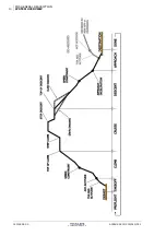
Page 625: ...AD MESSAGES 8 Chapter 2 MCDU NAMING and FORMAT 2 1 Waypoint abbreviations 3 2 2 Flight Plan Markers 12 2 3 MCDU prompts 13 2 4 F PLN page lateral defining legs 14 2 5 Pilot entries Data format 19 Chapter 3 FMS RESETS SUMMARY Chapter 4 OPC and AMI files Chapter 5 ND SYMBOLS 5 1 NAVIGATION LATERAL SYMBOLS 3 5 2 VERTICAL AND PERFORMANCE SYMBOLS 5 Chapter 6 ABBREVIATIONS AIRBUS A318 319 320 321 THALES...

Page 626: ...APPENDICES 2 CONTENT PAGE INTENTIONALLY LEFT BLANK J43126AA 00 THALES AVIONICS S A AIRBUS A318 319 320 321 ...
Page 627: ...CHPAD MESSAGES 3 Type I Type II messages 3 Definition 3 Illumination of FMS annunciator 3 TYPE II messages Conditions for display 4 1 3 MESSAGE DELETION 5 1 4 PFD FM MESSAGES 6 1 5 ND FM MESSAGES 6 Center of ND 6 Bottom of ND 7 1 6 MCDU SCRATCHPAD MESSAGES 8 AIRBUS A318 319 320 321 THALES AVIONICS S A J43126AA 00 ...

Page 628: ...APPENDICES 2 MESSAGES PAGE INTENTIONALLY BLANK J43126AA 00 THALES AVIONICS S A AIRBUS A318 319 320 321 ...

Page 629: ...o prompt a pilot action Type II messages are stored in a message queue with the following logic The last message entered in the queue is displayed if it is not inhibited If it is inhibited the first non inhibited message from top to bottom of the queue is displayed A maximum of 5 messages can be stored Only one occurrence of a given message is generated it is placed on the top of the queue and any...

Page 630: ...ations A Type II message displayed in the scratchpad is removed if data is entered The message returns when scratchpad is emptied A Type II message generated while data or a Type I message is occupying the scratchpad is displayed only when the scratchpad is cleared If a Type II message is cleared from the scratchpad then the next one in the queue is displayed J43126AA 00 THALES AVIONICS S A AIRBUS...

Page 631: ...r page key is pressed Specific conditions Some Type II messages are automatically cleared from the queue when they no longer apply At transition to DONE Phase Messages are cleared from the scratchpad and the message queue at transition to DONE flight phase Other messages may be displayed during DONE phase if appropriate Messages which are displayed on both scratchpad and PFD ND are cleared simulta...

Page 632: ...er of ND MODE CHANGE green If there is a discrepancy between t selected mode on the EFIS cont panel and the mode sent from the onside FMGC or while the DMC is preparing a new page for display he rol ANGE CHANGE green R tween the he e has AP NOT AVAIL red If there is a discrepancy be range selected on the EFIS control panel and the range sent from t onside FMGC A MODE CHANGE messag priority over a ...

Page 633: ...VOR D UNAVAIL amber With associated scratchpad message Navaid tuned for the selected approach or departure is not available SET OFFSIDE RNG MODE amber Displayed on ND1 2 in case of an FMGC1 2 failure when the two ND ranges or modes selected on the EFIS control panels are different GPS PRIMARY white boxed white With associated scratchpad message This message appears when GPS PRIMARY mode is availab...

Page 634: ... PRIMARY GPS PRIMARY LOST 1 6 MCDU SCRATCHPAD MESSAGES The MCDU scratchpad messages are described in the table below They are listed in alphabetic order For each message the table gives Message text Type I or II Color A amber W white Display on PFD ND Y yes message is inhibited during takeoff approach and go around below 800 ft D Specific Data Link message Message definition J43126AA 00 THALES AVI...

Page 635: ...r the AMI RNP value becomes smaller than the active pilot entered value 124 AWY WPT MISMATCH W Y Displayed when entering an AIRWAY AWY entered under VIA does not contain the revised WPT or The ending point does not belong to the airway 51 CABIN RATE EXCEEDED FM II W This message is displayed when all of the following conditions exist in CRZ flight phase and within 200NM of the destination along th...

Page 636: ...ed message re appears if conditions still exist 202 CHECK IRS1 FM POSITION II A IRS 1 has abnormal drift 47 CHECK IRS2 FM POSITION II A IRS 2 has abnormal drift 96 CHECK IRS3 FM POSITION II A IRS 3 has abnormal drift 97 CHECK QFE II A Y Flight phase is Descent or Approach a QNH value has been entered on the Approach Page QFE has been selected and QFE height differs by more than 100ft from the pred...

Page 637: ...the following conditions are true A C is in climb or cruise phase and A C is beyond the T D point and A C is in managed speed This message may only appear once per T D sequence 7 DEST ALTN MISMATCH I W Y Pilot enters an ALTN CO RTE of which origin does not match primary destination 49 DIR TO IN PROCESS I W Y A temporary flight plan exists due to a DIRECT TO INTERCEPT revision and a revision other ...

Page 638: ...h side is Less than or equal to 0 3NM when GPS mode is not active Less than or equal to 3NM when GPS mode is not active 21 FMS1 FMS2 SPD TGT DIFF II W Target speeds computed by the FMGs differ by 5KT or more 67 FORMAT ERROR I W Y Pilot entry in a data field exceeds the field width or is of incorrect format or type May be due to an inadvertent insertion of a space character 24 F PLN DATALINK IN PRO...

Page 639: ... D Errors occurred during the decoding process uplink F PLN message is rejected 101 INVALID PERF UPLINK II W Y D Displayed if uplink PERF message is rejected 109 INVALID TAKEOFF UPLINK II W Y D Displayed if uplink TO message is rejected 111 INVALID WIND UPLINK II W D Displayed if uplink WIND message is rejected 113 IRS ONLY NAVIGATION FM II A Y In enroute area or transitioning to descent or approa...

Page 640: ... so that constraint altitude no longer limits THR RED ALT the THR RED ALT does not move back to its original value but remains limited to the previous constraint 40 NO ANSWER TO REQUEST II W D No answer to downlink request within 4 minutes resulting in time out condition A time out condition occurs If an uplink message is received after a timeout occurs on the downlink request this message is proc...

Page 641: ...phase 60 OPP FMGC IN PROCESS II A Y The onside FMGC has failed and the OPP FMGC is selected on the MCDU MENU Page 204 OWN FMGC IN PROCESS II W Y The OWN FMGC is selected on the MCDU MENU Page Also displayed when the onside FMGC has failed and recovered and the OWN FMGC is selected on the MCDU MENU Page 206 PERF DATA UPLINK II W Y D A PERF uplink message containing complete or partially valid data ...

Page 642: ...M I W Displayed when MCDU displays its MENU page 46 SELECT HDG TRK FIRST I W Y With NAV mode engaged The TMPY F PLN diverges from the ACTIVE F PLN and a TMPY activation is attempted The SEC F PLN and ACTIVE F PLN are divergent and a SEC F PLN activation is attempted If an Offset is defined and SEC F PLN is activated Offset is deleted 406 SENSOR IS INVALID I W Y FF or FQ is entered or cleared on th...

Page 643: ...ds SPEED LIMIT by 10KTs and ALT is within 150 ft of SPEED LIMIT ALTITUDE Message is cleared when speed no longer exceeds the SPEED LIMIT 5KTs 4 SPECIF NDB UNAVAIL II A Y Auto tuned NDB is not available 57 SPECIF VOR D UNAVAIL II A ND Y Auto tuned VOR VOR DME VORTAC is not available 68 STEP ABOVE MAX FL II W STEP ALT exceeds the Max Max ALT based on predicted gross weight at the step start point 80...

Page 644: ...st leave holding immediately to satisfy fuel reserve requirements Extra fuel is zero 82 TMPY F PLN EXISTS I W Y Pilot attempts to enter a CO RTE FROM TO ALTN Airport or Route or to activate SEC F PLN while a TMPY F PLN exists 34 TOO STEEP PATH AHEAD II A A too steep path is detected in the computed descent profile and NAV mode engaged in DES or APPR or CRZ phase within 150Nm of destination This me...

Page 645: ... review in either flight plan 112 WIND UPLINK EXISTS I W Y D A flight plan modification ACTIVE or SEC is attempted while uplink winds are not yet inserted 115 XXXX IS DESELECTED I W Y XXXX NAME OF NAVAID or NUMBER of a SATELLITE Pilot attempts to deselect a navaid or a satellite which is already de selected 53 AIRBUS A318 319 320 321 THALES AVIONICS S A J43126AA 00 ...

Page 646: ...APPENDICES 20 MESSAGES PAGE INTENTIONALLY BLANK J43126AA 00 THALES AVIONICS S A AIRBUS A318 319 320 321 ...

Page 647: ...s 3 Pilot defined WPTs 4 LAT LONG LLXX or NXXEXXX 5 PLACE BRG DIST PBD 7 PLACE BRG PLACE BRG PBX 8 PLACE DIST PD 8 Abeam reference point AB 9 Pseudo Waypoints 10 2 2 Flight Plan Markers 12 2 3 MCDU prompts 13 2 4 F PLN page lateral defining legs 14 2 5 Pilot entries Data format 19 AIRBUS A318 319 320 321 THALES AVIONICS S A J43126AA 00 ...

Page 648: ...APPENDICES 2 MCDU NAMING and DATA FORMAT PAGE INTENTIONALLY BLANK J43126AA 00 THALES AVIONICS S A AIRBUS A318 319 320 321 ...
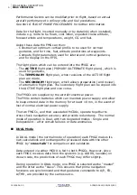
Page 649: ...hows DEP LFBO and ARR EGLL with two different providers FROM THV001 FIST5A TIME SPD ALT LFBO14R 0000 141 490 C144 BRG144 1 1000 0000 153 1000 C144 TRK142 4 TOU8 0002 250 3130 TOU144 2 4000 0002 4000 C311 7NM INTCPT 0004 FL88 DEST TIME DIST EFOB EGLL27R 0121 543 4 5 FROM THV001 FIST5A TIME SPD ALT LFBO14R 0000 141 490 HC144 BRG144 1 900 0000 153 900 C144 TRK144 4 D144H 0002 3130 C356 8 TOU 0005 250...

Page 650: ...shown alphabetic keys may be counted to determine the distance in NM which the letter relates to Pilot defined WPTs Certain pilot entered waypoints in the flight plan are automatically abbreviated They are LAT LONG PLACE BRG DIST PLACE BRG PLACE BRG and PLACE DIST pilot defined waypoints Radial Intercept and abeam reference points J43126AA 00 THALES AVIONICS S A AIRBUS A318 319 320 321 ...
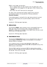
Page 651: ... FL360 UN874 30 BOKNO 0745 FL360 UN874 27NM DEVRO 0748 FL360 DEST UTC DIST EFOB EGLL27R 0836 416 3 8 4600N 100E If the OPC option WAYPOINT ABBREVIATION is LLXX When pilot defines a waypoint by LAT LONG the FM abbreviates it to LLXX where XX is a two digit number indicating the number of the LAT LONG definition LLXX becomes the waypoint i and may be used as any other waypoint identifier de ecomes n...

Page 652: ...lection A waypoint defined this way becomes one of the 20 pilot defined waypoints Caution LAT REV FROM N46E001 46 00 0N 001 00 0E NEXT WPT HOLD ENABLE NEW DEST ALTN TMPY F PLN FROM TMPY THV001 UTC SPD ALT T P 0629 FL360 BRG329 27 FOUCO 0734 79 FL360 TRK059 26 N46E001 0739 F PLN DISCONTINUITY ADABI 0744 79 TMPY TMPY ERASE INSERT NEW WAYPOINT IDENT N46E001 LAT LONG 4600 0N 0100 0E RETURN STORE FROM ...

Page 653: ... this to PBDNN where NN is a two digit number indicating the number of the PLACE BRG DIST definition PBDNN becomes the identifier of the waypoint and may be used as for any other waypoint identifier A waypoint defined this way becomes one of the 20 pilot defined waypoints NN is the first number between 01 and 20 which is not already used for another pilot defined waypoint abbreviation in that list...

Page 654: ...0 TRK356 49 PBX01 1209 F PLN DISCONTINUITY ADABI 1210 79 TMPY TMPY ERASE INSERT PLACE DIST PD If the flight crew defines a waypoint as a PLACE DIST i e along track offset on the F PLN pages the FM abbreviates this to PDNN where NN is to two digit number indicating the number of the PLACE DIST waypoint definition PDNN becomes the identifier of the waypoint and may be used as for any other waypoint ...

Page 655: ...sed he BXXXXX becomes the identifier be A of the waypoint and may used as for any other waypoint identifier However this waypoint does not become one of the twenty pilot defined waypoints DIR TO WAYPOINT UTC DIST ADABI 1224 75 F PLN WPTS ADABI DIRECT TO WITH BOKNO ABEAM PTS RADIAL IN DEVRO 184 RADIAL OUT VANAD DIR TO DIR TO ER INSERT ASE THV001 UTC SPD ALT ABFOUCO 1217 79 FL360 48 ADABI 1224 UN874...

Page 656: ...o waypoints are contained in parentheses when displayed on the F PLN pages of the MCDU Predictions on F PLN A page are provided for all pseudo waypoints On the F PLN B page only distance and EFOB are provided except for T C and T D pseudo waypoints where forecast winds are also provided The SPD LIM S C and S D pseudo waypoints can be cleared by the CLR key via either the right or left LS key THV00...

Page 657: ... point where the step climb starts For a step at waypoint it is displayed on the line below that waypoint No No Yes S D 1 Step Descent point Inserted into the F PLN at the point where the step descent starts For a step at waypoint it is displayed on the line below that waypoint No No Yes SPD LIM 1 Speed limit This is an altitude related speed limit The speed limit is inserted into the F PLN at the...

Page 658: ... F PLN The end of the alternate flight plan No No No NO ALTN F PLN There is no alternate flight plan No No No TOO STEEP PATH The start of a Too Steep Path in the vertical F PLN No No No ABEAM PTS There is a pending Direct To with abeam points revision No No No 1 A discontinuity cannot be cleared between the origin and destination when the origin and destination waypoints are the same and there are...

Page 659: ...sion in the TMPY F PLN Part III 2 2 TMPY INSERT Activates the TMPY F PLN Part III 2 2 TMPY ERASE Deletes the whole TMPY F PLN Part III 2 2 DIR TO INSERT Activates the TMPY F PLN in case of pending Direct To revision Part III 3 3 DIR TO ERASE Deletes the TMPY F PLN in case of pending Direct To revision Part III 3 3 CLB Assigns the entered constraint to the climb segment Part III 4 1 DES Assigns the...

Page 660: ...ta base in accordance with ARINC 424 specification It indicates access from LAT VERT revision WPT represents any waypoint name FROM THV001 FIST5A TIME SPD ALT LFB014R 0000 141 490 H144 BRG144 1 900 0000 153 900 C144 TRK144 4 D144H 0002 3130 C356 8 TOU 0005 250 FL85 SPD 3NM LIM 0005 250 FL100 DEST UTC DIST EFOB EGLL27R 0122 532 4 4 J43126AA 00 THALES AVIONICS S A AIRBUS A318 319 320 321 ...
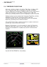
Page 661: ...e Y Y DDNAV WPT AF DD is the distance of the arc NAV is the first three characters of the DME station identifier from which arc is defined from WPT is the terminating waypoint Y Y HOLD L HHHHH 3 HA L R is direction of turn HHHHH terminating altitude Y Y HOLD L CXXX WPT 1 HM L R is direction of turn XXX is the inbound course to the holding pattern fix WPT is the holding pattern fix which may be a f...

Page 662: ...haracters of the DME station identifier from which distance is defined DD is DME distance Y Y WPT DD VD DME HXXX INTCPT VI XXX is heading The following leg defines the intercept termination Y 5 Y VI 070 H090 DDARC WPT RF DD is the radius of the arc WPT is the termination waypoint Y Y RF DD WPT PROC INTCPT CXXX WPT PI CF XXX is the inbound course to the procedure turn fix Y 4 Y CF INTCPT PI J43126A...

Page 663: ...is the first three characters of the identifier of the fixed waypoint from which the course is defined XXX is the outbound course from the previous waypoint Y Y T P Fixed WPT Turn Point Displayed when a Direct To hold or offset revision at present position is pending or inserted It becomes a fixed waypoint at the LAT LONG when the temporary F PLN is inserted Y Y IN BND Fixed WPT Turn Point Display...

Page 664: ...X is course WPT is the first three characters of the identifier of the fixed waypoint from which the course is defined RRR is radial from WPT Y Y CI Notes 1 Signifies that pilot may insert this leg in F PLN All other legs can only be entered from the Navigation Data Base 2 Access from WPT only 3 Altitude termination may be displayed as flight level FLHHH or altitude HHHHH Leading zeros are suppres...

Page 665: ... s pad msg white is triggered This may be due to an inadvertent insertion of a space character RANGE Range is given for each data entry according to the unit chosen When Pilot entry is of correct field width format and type but is not within acceptable range ENTRY OUT OF RANGE s pad msg white is displayed unless another message is already displayed UNITS Units are given for each entry When two uni...

Page 666: ...RPT IDENT may be less than 4 characters If AAAA is not in the Data Base airport file NEW RUNWAY page is displayed INIT A SEC INIT A LAT REV ALTN BLOCK FUEL NN N if OPC option is Kg NNN N if OPC option is lb Leading zeros may be omitted 0 Max block as defined in aero model versus center tank program pin Thousands of Kg or lb OPC option INIT B CABIN RATE NNN or NNN 100 to 999 100 to 999 in 1 ft mn i...

Page 667: ... TEMP See TEMP See TEMP INIT A SEC INIT A FUEL PRED DH NNN NO may be entered 0 700 ft PERF APPROACH DIST NN N Leading and trailing zeros may be omitted NNNN 0 99 9 in 0 1 NM increments 0 9999 in 1 NM increments NM NM HOLD ALTN DRT TO D NN Eight possible values See Part II 2 1 PERF TAKE OFF ELV NNNNN If or is not input assume Leading zeros may be omitted 2000 to 20470 ft MSL NEW NAVAID NEW RUNWAY E...

Page 668: ...s TEMP NN in degrees centigrade TAKE OFF FLIGHT LEVEL FLNNN or NNN Leading zeros on NNN may be omitted 1 Max Certified Altitude 100 Hundreds of ft STD F PLN A PROG VERT REV INIT A SEC INIT A SEC F FPLN A STEP ALTS PERF CLB PERF DES CLB WIND CRZ WIND DES WIND FLT NBR XXXXXXXX Up to 8 alphanumeric characters may be entered N A INIT A FOB NN NN if OPC option is Kg NNN N if OPC option is lb Leading ze...

Page 669: ...es LAT REV LAT DDMM MB or BDDMM M DD degrees MM M minutes B direction Leading zeros may be omitted but the direction B N or S is necessary Latitude is displayed as DDMM MB B N or S DD 90 MM M 59 9 Degrees Minute Tenths of minutes INIT A LAT LONG LAT LONG Same as LAT and LONG except both must be entered with in between Same as LAT and LONG Same as LAT and LONG PROG F PLN A B NEW WPT NEW NAVAID NEW ...

Page 670: ... will always be displayed as BNN B L or R 0 NN 50 NM OFFSET PERF FACTOR N N Leading or trailing zero may be omitted 9 9 9 9 A C STATUS PLACE BRG DIST PLACE can be any data base or pilot defined ARPT RWY NAVAID or WAYPOINT Entry without decimal digit An entry of BRG 360 is displayed as 0 DIST is NNN N where leading zeros may be omitted all 3 parameters must be entered with between entries PLACE if ...

Page 671: ...2 00 31 01 In Hg Hecto Pascals In Hg APPROACH RADIAL IN NNN Leading zeros may be omitted An entry of 360 is displayed as 0 000 360 Degrees DIR TO RADIAL OUT NNN Leading zeros may be omitted An entry of 360 is displayed as 0 000 360 Degrees DIR TO REQUIRED ACCUR NN NN Leading or trailing zero may be omitted 0 01 20 0 NM PROGRESS UTC CSTR HHMMSS or HHMM 0 23 0 59 0 59 H MN S VERT REV RTE RSV RTE RSV...

Page 672: ...Q SLOPE N N 0 0 9 9 Degrees NEW NAVAID SPD NNN Must be 3 numeric characters MAX VMO MIN 100 KT KT CAS F PLN A SEC F PLN A VERT REV PERF CLB PERF CRZ PERF DES SPD LIM SSS NNNNN SSS is a speed NNNNN is an ALT or FLIGHT LEVEL see ALT and FLIGHT LEVEL SSS same as SPD KT ft MSL or KT FL VERT REV F PLN A SPD MACH See MACH SPD Same as MACH and SPD Same as MACH and SPD PERF DES STATION DEC NNND NNN is the...

Page 673: ...T Same as ALT ft MSL TAKE OFF APPROACH TRIP WIND See EFF WIND KT INIT B SEC INIT B TROPO An entry of NNNN or NNNNN is considered as an ALTITUDE An entry of NNN or NN is considered as a FLIGHT LEVEL ALT 1000 99990 Altitude entry is rounded to the nearest 10 feet FL 10 999 Same as ALT or FLIGHT LEVEL FUEL PRED INIT A SEC INIT A UPDATE AT Same as WAYPOINT Same as WAYPOINT N A PROG V1 Same as SPD KT C...

Page 674: ...s ALT Degrees KT ft MSL CLIMB WIND CRUISE WIND DESCENT WIND ZFW NN N if Kg unit NNN N if lb Unit Leading and trailing zeros may be omitted 35 Max ZFW if Kg unit Thousands of Kg or lb OPC option INIT B ZFWCG Same as CG Same as CG Same as CG INIT B Note 1 An entry with a Back Beam B or a Front Beam F indicator is allowed for an ILS course If the Back Course Take Off option and if the Back Beam Appro...

Page 675: ...APPENDICES FMS RESETS 1 Part V Chapter 3 FMS RESETS SUMMARY Contents AUTO RESET OF ONE FMGC 2 AUTO RESET of BOTH FMGCs 3 AIRBUS A318 319 320 321 THALES AVIONICS S A J43126AA 00 ...

Page 676: ...message amber momentarily displayed on scratchpad ECAM and AURAL warning if AP disconnects Red warning AUTO FLT AP OFF and aural warning Red warning AUTO FLT AP OFF and aural warning if A THR disconnects Amber caution AUTO FLT A THR OFF and aural warning Amber caution AUTO FLT A THR OFF and aural warning RECOVERY FMS All data in affected FM are saved All data in affected FM are erased but through ...

Page 677: ...R disconnects Amber caution AUTO FLT A THR OFF and aural warning RECOVERY FMS All FM data are saved All FM data are lost The affected FM position is reinitialized to the IRS position and the EPE is set to zero If GPS option is activated in the OPC file the GPS is automatically selected All deselected navaids are erased AP A THR Re engage as necessary MCDU If MCDU MENU page is displayed Select FMGC...

Page 678: ...APPENDICES 4 FMS RESETS PAGE INTENTIONALLY LEFT BLANK J43126AA 00 THALES AVIONICS S A AIRBUS A318 319 320 321 ...
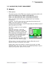
Page 679: ...APPENDICES OPC and AMI FILES 1 Part V Chapter 4 OPC and AMI FILES Contents 4 1 OPC FILE 3 4 2 AMI FILE 4 AIRBUS A318 319 320 321 THALES AVIONICS S A J43126AA 00 ...

Page 680: ...APPENDICES 2 OPC and AMI FILES PAGE INTENTIONALLY BLANK J43126AA 00 THALES AVIONICS S A AIRBUS A318 319 320 321 ...

Page 681: ... IRS HDG INITIALIZATION Option activated Y N N LAT LONG abbreviation type L LLxx N NxxWyyy L MINI ACARS Option LIMITED AOC OPTION BROADCAST DATA ONLY AOC PROMPT IS NOT DISPLAYED Y N N PRINTER INSTALLED Y N N DECEL 2 activated D CIRCLED IN MAGENTA D CIRCLED IN WHITE Y N N NAV_POLICY_OPTIONS EN ROUTE default RNP value 2 Oceanic default RNP value 0 01 20 TERMINAL default RNP value 1 GPS APPROACH defa...

Page 682: ...nce Adjustement Code 3 characters ARM Fuel for taxi 0 2000 kg 200 Percentage of trip fuel for route reserves 0 15 5 Upper limit for route reserves quantity 0 10000 kg 10000 Lower limit for route reserves quantity 0 10000 kg 0 Compute route reserve during flight Y N Y Alternate trip included in route reserve Y N N Time in which final holding pattern supposed to be flown Used for fuel prediction 0 9...

Page 683: ...eport inhibit Y N Y inhibit Y Delta ETA Trigger 0 59 mn 0 Flight plan FPN FPC Report inhibit Y N Y inhibit Y Rejection message enable Y N N inhibit N Response message enable Y N N inhibit N Auto print of AOC Uplinks enable Y N N inhibit N Auto print of Flight Plan Uplink default setting Y N N no default N Auto print of Take Off Data Uplink default setting Y N N no default N Auto print of Wind Upli...

Page 684: ...APPENDICES 6 OPC and AMI FILES PAGE INTENTIONALLY BLANK J43126AA 00 THALES AVIONICS S A AIRBUS A318 319 320 321 ...
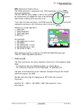
Page 685: ...APPENDICES ND SYMBOLS 1 Part V Chapter 5 ND SYMBOLS Contents 5 1 NAVIGATION LATERAL SYMBOLS 3 5 2 VERTICAL AND PERFORMANCE SYMBOLS 5 AIRBUS A318 319 320 321 THALES AVIONICS S A J43126AA 00 ...

Page 686: ...APPENDICES 2 ND SYMBOLS PAGE INTENTIONALLY LEFT BLANK J43126AA 00 THALES AVIONICS S A AIRBUS A318 319 320 321 ...
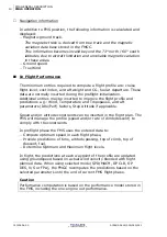
Page 687: ...VE F PLN is shown by a continuous green line when NAV mode is engaged TMPY F PLN shown by a dashed yellow line SEC F PLN is shown by a continuous white line Missed approach procedure is shown by a continuous blue line ALTN F PLN is shown by a dashed blue line EOSID when available is shown by a continuous yellow line F PLN Cross track error The TO WPT with label is shown in white Waypoints The en r...

Page 688: ...rns These appear only when they are part of the flight plan For the 160 and 320 NM range scales each one is shown by a white arrow that originates at the associated fix and indicates the direction of the turn For shorter range scales and if the procedure turn or the holding pattern is in the next or the active leg the display shows the full circuit or pattern J43126AA 00 THALES AVIONICS S A AIRBUS...

Page 689: ...tercept point symbol White if only the NAV mode is engaged Blue if DES mode is engaged Indicates the point at which the aircraft is predicted to intercept the descent path if there is any vertical deviation while the aircraft is in DES mode Speed change symbol Indicates the point at which an automatic acceleration or deceleration starts to comply with SPD LIM SPD CSTR or HOLDING SPD Decelerate poi...

Page 690: ... taken into account by the guidance and NAV mode is engaged Vertical constraints Vertical constraints at a WPT ALT SPD TIME constraints displayed in magenta if CSTR is selected on EFIS control panel ENERGY CIRCLE symbol Is centered on the aircraft position and oriented to the current track line Represents the Required Distance to Land Only displayed in the descent and approach phases when a select...

Page 691: ...Data Module ADR Air Data Reference ADV Advisory AFS Auto Flight System AGL Above Ground Level AIDS Aircraft Integrated Data System AIME Autonomous Integrity Monitoring Extrapolation ALT Altitude ALTN Alternate airport AMI Airline Modifiable Information AMU Audio Management Unit ANN Annunciator ANP Actual Navigation Performance ANT Antenna AOC Airline Operational Control AP Autopilot APPR Approach ...

Page 692: ... Company CO RTE Company route CONT Continuous CRS Course CRT Cathode Ray Tube CRZ Cruise CSTR Constraint CTL Control CTL PNL Control Panel CTR Center DA Drift Angle DCDU Datalink Control and Display Unit DDRMI Digital Distance and Radio Magnetic Indicator DECEL Deceleration DEG Degree DEP Departure DES Descent DEST Destination DFDR Digital Flight Data Recorder DH Decision Height DIR Direction DIR ...

Page 693: ...d position Error EPR Engine Pressure Ratio EPU Estimated Position Uncertainty EROPS Extended Range Operation ESS Essential EST Estimated ETA Estimated Time ar Arrival ETE Estimated Time Enroute ETOPS Extended Twin Operation ETP Equal Time Point ETT Estimated Time for Take Off ETX End of Transmission EXP Expedite EXT PWR External Power EXTN Extension F Fahrenheit Flap retraction speed F C Flight Cr...

Page 694: ...A Flight Path Angle FPD Fight Path Director FPV F PLN Flight Plan FPPU Feedback Position Pick off Unit FPV Flight Path Vector FQI FQU Fuel Quantity Indication Unit FREQ Frequency FRT Front FRV Fuel Return Valve FT Foot Feet FT MN Feet per Minute FU Fuel Used FWC Flight Warning Computer FWD Forward FWS Flight Warning System G Green G DOT Green Dot G S Glideslope GA Go around GC Great Circle GMT Gre...

Page 695: ...ce System PART OF ADIRS ISA International Standard Atmosphere ISDU IRS System Display Unit ISO International Organization for Standardization ISOL Isolation KG Kilogram KT Knot KT Knot L Left L G Landing Gear LAT Latitude LAT REV Lateral Revision LCN Load Classification Number LDA Localizer type Directional Facility LDG Landing LF Low Frequency LH Left Hand LHS Left Hand Seat LIM Limitation LIS Lo...

Page 696: ...de MDH Minimum Descent Height MDDU Multifunction Disk Drive Unit MECH Mechanic MED Medium MEL Minimum Equipment List MIN Minimum Minute MIN FUEL Minimum Fuel MIN TIME Minimum Time MKR Marker MLS Microwave Landing System MLW Maximum Landing Weight MMEL Master Minimum Equipment List MMO Maximum Operating Mach MMR Multi Mode Receiver MN Mach Number MORA Minimum OFF Route Altitude MRP MAP Reference Po...

Page 697: ...d OUTR Outer OVFY Overfly OVHD Overhead OVRD Override OVSPD Overspeed OXY Oxygen P N Part Number P P Previous Page PA Passenger Address P ALT Profile Altitude PAX Passenger PB pb Pushbutton P CLB Profile Climb P DES Profile Descent PDU Pilot Display Unit PERF Performance PF Pilot Flying PFD EFIS Primary Flight Display P MACH Profile Mach PNF Pilot Non Flying PNL Panel POS Position PPOS Present Pos...

Page 698: ... RDY Ready REAC Reactive RED Reduction REF Reference REG Regulation REL Release REQ Request REV Reverse RH Right Hand RHS Right Hand Seat RLSK Right Line Select Key RMI Radio Magnetic Indicator RMP Radio Management Panel RMP Radio Management Panel RNAV RNAV procedure RNG Range RNP Required Navigation Performance RPM Revolution Per Minute RPTG Repeating RQRD Required RSV Reserves RTA Required Time ...

Page 699: ...l Arrival Route STAT Static STAT INV Static Inverter STBY Standby STD Standard STS Status STX Start of Transmission SW Switch SWTG Switching SYN Synchronize Transmission Not Understandable SYNC Synchronize SYS System T Tons Temperature True Turn Total T True T O T O Takeoff T C Top of Climb T D Top of Descent T L Thrust Levers TACAN Ultra high Frequency Tactical Air Navigation Aid TACT Tactical TA...

Page 700: ...ilure Speed V2 Takeoff Safety Speed VD Heading to a DME Distance VDEV Vertical Deviation VEL Velocity VERT REV Vertical Revision VFE Maxi Velocity Flaps Extended VFEN VFE Next VFTO Velocity Final Takeoff VHF Very High Frequency VI Heading to an Intercept VIB Vibration VLE Maximum Landing Gear Extended Speed VLS Lowest Selectable Speed VMAN Maneuvering speed VMAX Maximum Allowable Speed VMCA Minimu...

Page 701: ...t and Balance System WGD Windshield Guidance Display WNDW Window WPT Waypoint WT Weight WXR Weather Radar XCVR Transceiver XFR Transfer XING Crossing XMTR Transmitter XPDR Transponder XTK Crosstrack Error Y Yellow Z Altitude ZFCG Zero Fuel Center of Gravity ZFW Zero Fuel Weight ZFWCG Center of Gravity without Fuel AIRBUS A318 319 320 321 THALES AVIONICS S A J43126AA 00 ...

Page 702: ...APPENDICES 12 ABBREVIATIONS PAGE INTENTIONALLY LEFT BLANK J43126AA 00 THALES AVIONICS S A AIRBUS A318 319 320 321 ...

Page 703: ...FLIGHT MANAGEMENT SYSTEM PILOT S GUIDE UNFOLD 1 AIRBUS A318 319 320 321 THALES AVIONICS S A J43126AA 00 ...

Reviews: