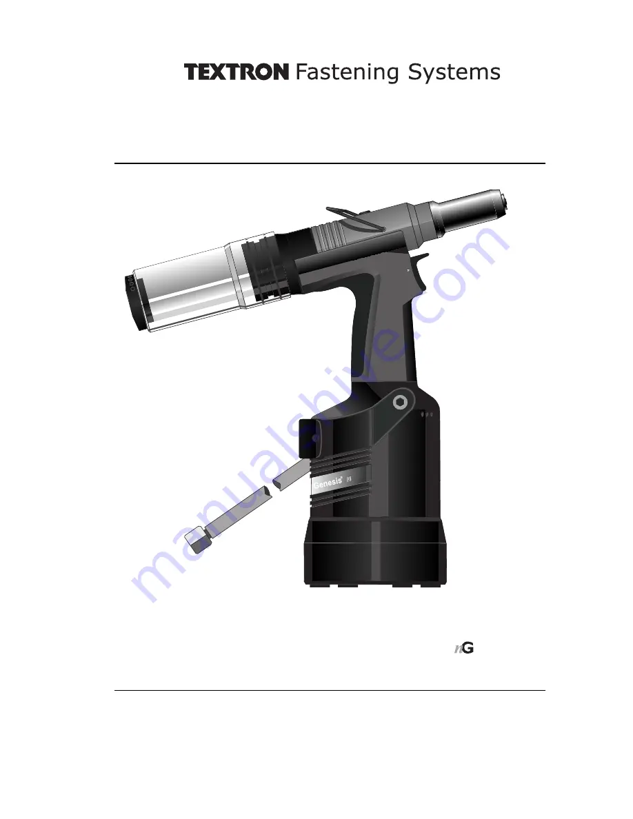
G4
H y d ro - P n e u m a t i c P o w e r To o l
Genesis
¨
I n s t r u c t i o n M a n u a l
Inc.
4
m o d e l
Textron Fastening Systems Inc. is a wholly owned subsidary of Textron Inc.
Page 1: ...G4 Hydro Pneumatic Power Tool Genesis Instruction Manual Inc 4 model Textron Fastening Systems Inc is a wholly owned subsidary of Textron Inc...
Page 2: ......
Page 3: ...l General Assembly 24 Parts List 25 Priming Oil Details 26 Hyspin VG 32 Oil Safety Data 26 Priming Kit 26 Priming Procedure 27 Fault Diagnosis Symptom Possible Cause and Remedy 28 Textron Fastening Sy...
Page 4: ...t operate a tool machine that is directed towards any person s or the operator 9 Always adopt a firm footing or a stable position before operating the tool machine 10 Ensure that vent holes do not bec...
Page 5: ...s 0 15 cu ft Stroke Minimum 17 mm Pull Force 5 5 bar 18 68 kN 4200 lbf Cycle Time Approximately 1 2 seconds Noise Level 75 dB A Weight Including nose equipment 2 3 kg Vibration Less than 2 5 m s2 Dime...
Page 6: ...AVSEAL II QTM RIVET TTM RIVET CHERRYMATETM 4 3 4 8 5 5 2 6 6 4 6 5 7 8 9 9 5 10 11 12 3 16 1 4 3 8 COMPLETE TOOL 71233 00 BASE TOOL 1 1 2 3 1 NOSE ASSEMBLY NOSE TIP 2 71233 02000 71210 15000 see note...
Page 7: ...PRESSURE REGULATOR AND FILTER DRAIN DAILY 3 METRES MAXIMUM Ensure that the correct nose assembly suitable for the fastener is fitted Connect the tool to the air supply Insert the fastener stem into t...
Page 8: ...s shown below Keeping the head of the stem against the application push the tool onto the protruding stem Fully depress the trigger One cycle will ensure that the collar is swaged into the lock groove...
Page 9: ...ompatible nose assembly and nose tip are fitted prior to operating the tool no nose tip with Maxlok Fitting Instructions All Nose Assemblies except Avtainer and Maxlok I M P O R T A N T The air supply...
Page 10: ...7 07381 04701 07340 04800 07490 04401 07340 066012 07612 02001 07381 04701 07381 04701 07381 04701 07340 04800 07612 02001 07381 04701 07605 00220 71220 16080 07498 01401 07340 06201 07340 06201 0749...
Page 11: ...SING 07430 00304 4 JAWS 71210 16101 5 JAW SPREADER 07498 04502 6 BUFFER 71210 05001 7 SPRING 07500 00418 8 LOCKING RING 07340 00327 N O S E A S S E M B L Y part n 71230 16100 ITEM DESCRIPTION PART N 1...
Page 12: ...nless Steel Any Any 3 16 3 16 3 16 3 16 3 16 2 5 2 5 2 4 5 1 4 6 12 7 12 7 12 7 12 7 12 7 71210 16036 71210 16037 71220 16038 07340 06901 07344 04701 4 8 4 8 4 8 4 8 4 8 AVDEL MBC MBC L C 2 9 3 2 9 4...
Page 13: ...E 07220 02104 7 SPRING 07610 02107 8 LOCKING RING 07610 02004 12 ANVIL 07610 02001 13 VAC SHUT OFF STOP NUT ASSY 71233 20200 ITEM DESCRIPTION PART N 9 CHUCK COLLET 07610 02102 4 JAWS 07610 02103 10 SP...
Page 14: ...t be fitted Item numbers in bold refer to the general assembly and parts list pages 26 27 Other items numbers refer to the Maxlok No Nose Tip table page 12 Remove Jaw Spreader Housing 41 O Ring 12 and...
Page 15: ...2 EXTENSION PART NUMBER 71210 20300 Fitted between the tool and the nose assembly the extension allows access into deep channels To fit the extension remove any nose assembly components Screw the inne...
Page 16: ...y with special attention to the jaws Lubricate with Moly Lithium grease before assembling Check for oil leaks and air leaks in the air supply hose and fittings Grease can be ordered as a single item t...
Page 17: ...sical form and water insolubility of the product the bioavailability is negligible Handling General ventilation is recommended Avoid skin and eye contact Storage Do not store with oxidizing agents Kee...
Page 18: ...ctions see the nose assemblies section pages 9 to 14 For a complete service of the tool we advise that you proceed with dismantling of sub assemblies in the order shown After any dismantling REMEMBER...
Page 19: ...e not to damage the cylinder bore Remove Seal Retainer 43 Push Lip Seal 8 and Bearing Tape 26 to the rear and out of Head Assembly 58 taking care not to damage the cylinder bore Remove Seal Housing 52...
Page 20: ...Assembly Using Spanner 07900 00672 and Location Spigot 07900 00671 Unscrew Clamp Nut 39 and remove together with Top Plate Assembly 44 together with Tie Rods 56 Transfer Tube Assembly 61 O Rings 14 an...
Page 21: ...gs 5 Assemble in reverse order to Dismantling Instructions noting the following Seals should be checked for damage and replaced if necessary lubricated with Molykote 55m grease Ensure Rotary Valve 38...
Page 22: ...4 and 5 Retain parts in place using grease Molykote 55 Place O Ring 4 into the recess of Cover Plate 6 retain in position using grease Molykote 55 Place Spring 7 into position locate using the recess...
Page 23: ...Notes Inc 23...
Page 24: ...9 44 51 B B 41 12 40 1 6 43 52 Assy 58 2 8 17 64 Assy 21 46 Assy 33 42 19 15 35 Assy 36 9 91 13 28 11 X 26 A 89 20 104 Assy 25 Assy 50 79 80 65 Assy 53 14 53 34 14 7 98 99 Assy 59 96 4 22 14 23 62 Ass...
Page 25: ...4 65 66 67 71 72 73 74 75 76 77 79 80 89 90 91 96 97 98 99 100 103 104 71210 02019 71213 02010 71210 02022 71210 02024 71221 02007 71233 02027 71213 02028 71230 03205 71210 02104 71210 02031 71221 020...
Page 26: ...igate immediately with water for several minutes Although NOT a primary irritant minor irritation may occur following contact Fire Flash point 232 C Not classified as flammable Suitable extinguishing...
Page 27: ...d screw orifice CARE SHALL BE TAKEN TO ENSURE THAT THE BLEED HOLE IS NOT DIRECTED TOWARDS THE OPERATOR OR OTHER PERSONNEL Switch air supply OFF at ON OFF Valve Assembly 62 Screw priming pump 07900 007...
Page 28: ...t component in nose assembly Identify and replace 9 to 14 Jaws will not release Build up of dirt inside the nose assembly Service nose assembly 9 broken stem of Jaw housing nose tip or nose casing fas...
Page 29: ...Notes Inc 29...
Page 30: ...Notes Inc 30...
Page 31: ...ndards EN ISO 12100 parts 1 2 BS EN ISO 8662 part 6 BS EN ISO 11202 BS EN ISO 3744 BS EN 982 ISO EN 792 part 13 2000 BS EN 983 following the provisions of the Machine Directive 89 392 EC as amended by...
Page 32: ...genhagen Tel 49 511 7288 0 Fax 49 511 7288 133 Email info avdel de ITALY Textron Sistemi di Fissaggio SRL Via Manin 350 21 It 20099 Sesto San Giovanni Milano Tel 39 02 262 9171 Fax 39 02 242 4956 Emai...