6
DRIFTLESS
SPRAYER
ASSEMBLY
Description of Parts
Throughout this manual, parts or assemblies that perform a specific function carry an identifying name.
The following lists names used in this manual, along with a description of their appearance and function.
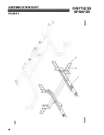
For further detail please refer to the general and plumbing assemblies located in the appendix.
Airfoil:
The white plastic piece mounted above the spray boom that runs the entire length of the boom.
The airfoil stabilizes air flow over the spray boom.
Shroud:
The large plastic body covering the sprayer. This enclosure houses the air cavity in which the
actual spraying is accomplished.
Curtain:
The curtain is composed of fabric hanging down from the shroud edge. The curtain seals the air
inside the shroud.
Wing:
The movable ends of the boom. The wing section breaks away from the center boom section
when the spray boom hits a large object. The wings break away to protect the object being
contacted, and the sprayer itself.
Center Frame:
The Center Frame supports the solution tank, supply pump, line strainer. The FM3500ST model
also includes the wing breakaway mechanisms and lift supports. The Center Frame attaches to
each spray boom section via float mechanisms.
Mount Adapter:
Adapts the Center Frame to fit your specific power unit.
First Checks
Your Front Mounted sprayer comes complete in one crate. The crate should include the following items:
1. Center spray section
2. Left and Right wing spray boom sections
3. Center castor frame
4. Center frame
5. Two Castor Wheel Assemblies
6. Assorted parts bag
7. Mount adapter
Look for the factory packing list attached to the shipping crate. Double check that this list has been
completely filled out and that you have all the items indicated by the list. If there are any problems
encountered please contact your dealer or the factory via the number indicated on the packing list.
Summary of Contents for 73-70675
Page 13: ...11 DRIFTLESS SPRAYER PARTS SECTION PARTS SECTION...
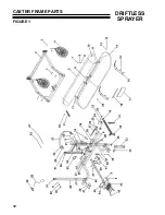
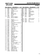
Page 14: ...12 DRIFTLESS SPRAYER CASTER FRAME PARTS FIGURE 1...
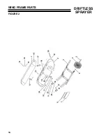
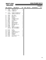
Page 16: ...14 DRIFTLESS SPRAYER WING FRAME PARTS FIGURE 2...
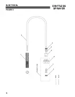
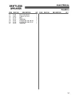
Page 18: ...16 DRIFTLESS SPRAYER ELECTRICAL FIGURE 3...
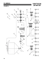
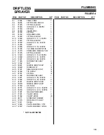
Page 20: ...18 DRIFTLESS SPRAYER PLUMBING FIGURE 4...
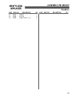
Page 22: ...20 DRIFTLESS SPRAYER ASSEMBLY FM MOUNT FIGURE 5...
Page 24: ...22 DRIFTLESS SPRAYER INSTALLATION SHEET FIGURE 6...
Page 26: ...24 DRIFTLESS SPRAYER CASTER WHEEL ASSEMBLY FIGURE 7...


