110
Operation:
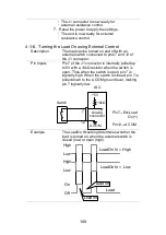
Configuration
1.
Press
Main
>
Configure [F5]
>
Next Menu
[F4]
>
External [F3]
and set the
LoadOn IN
setting.
Set to Low if you want the load to be turned on
when the switch is closed.
Set to High if you want the load to turn on when
the switch is open.
Note
When external control is used to turn the load
off, the load key cannot be used to turn the load
on. However the reverse is not true. If the load
has been turned on by external control, the load
key can be used to turn the load off.
4-1-7. Load On/Off Status
Description
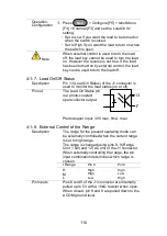
Pin 13 (Load On Status) of the J1 connector is
used to monitor the load status (on or off).
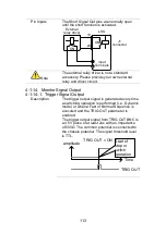
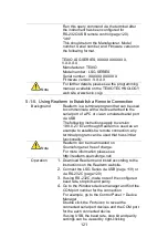
Pin out
The Load On Status pin
is a photo-coupled
open-collector output.
17
13
Photocoupler input: 30V max, 8mA, max.
4-1-8. External Control of the Range
Description
The range for the present operating mode can
be externally controlled when the current range
is set to high range.
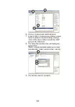
The range is changed using pins 8, 9 (Range
Cont 1 &0) and 12 (A Com) of the J1 connector.
When externally controlling the range, the pin
input combination determines which range is
chosen.
I Range
Pin 9
Pin 8
H
High
High
M
High
Low
L
Low
High
Pin Inputs
Pins 8 and 9 of the J1 connector are internally
pulle
d up to 5V with a 10kΩ resistor when open.
When closed, pin 8 and 9 are pulled down to the
A COM ground level.
Summary of Contents for LSG SERIES
Page 8: ......
Page 23: ...11 GRA 414 E EIA standard 132 382 5 477 6 GRA 414 J JIS standard 149 382 5 477 6 ...
Page 149: ...137 7 6 Operating Area LSG 175 ...
Page 150: ...138 LSG 350 ...
Page 151: ...139 LSG 1050 ...
Page 166: ......

