ADC Configuration Examples
313
SNIU028A – February 2016 – Revised April 2016
Copyright © 2016, Texas Instruments Incorporated
ADC12 Overview
NOTE:
The raw (not averaged) result of AD07 is being read here.
void poll_adc(void)
{
if(AdcRegs.ADCSTAT.bit.ADC_INT == 1) //If the conversion isn’t complete
{
adc_values.Vout = AdcRegs.ADCAVGRESULT[0].bit.RESULT;
// AD01
adc_values.isec = AdcRegs.ADCAVGRESULT[1].bit.RESULT;
// AD02
adc_values.i_pri = AdcRegs.ADCAVGRESULT[2].bit.RESULT;
// AD04
adc_values.ishare = AdcRegs.ADCAVGRESULT[3].bit.RESULT; // AD05
adc_values.Vin = AdcRegs.ADCAVGRESULT[4].bit.RESULT;
// AD05
adc_values.current_temp = AdcRegs.ADCAVGRESULT[5].bit.RESULT; // AD12
adc_values.temp_sense = AdcRegs.ADCRESULT[6].bit.RESULT;
// AD07
}
AdcRegs.ADCCTRL.bit.SW_START = 1;
// trigger anew measurement sequence
}
Now poll_adc(); can be called from any part of the code that is periodically executed. In this example the
function call is placed in the standard interrupt which is invoked by a timer interrupt in 100µs intervals.
Since conversion of a sequence of 6 measurements will require less than 30µs, the verification of end of
conversion is not really required.
#pragma INTERRUPT(standard_interrupt,IRQ)
void standard_interrupt(void)
{
poll_adc();
}
8.16.3 Auto-Triggered Conversions
A conversion sequence may also be initiated via external triggers without firmware initiation. Sources of
external triggering include the DPWM outputs, the analog comparators and the ADC_EXT_TRIG pin. The
sequencer operation is defined by the external trigger enable bit in the ADC Control Register. The single
sweep bit can set the sequencer in one of two modes, (1) start/stop or (2) continuous conversion on the
external trigger event. Some key points to note:
•
Only one external trigger can be enabled
•
A software trigger via the embedded processor is also regarded as a valid trigger
•
If an external trigger event occurs but the current sequence has not been completed, the event is
skipped until the next trigger event occurs when the sequencer is ready
8.16.4 Continuous Conversions
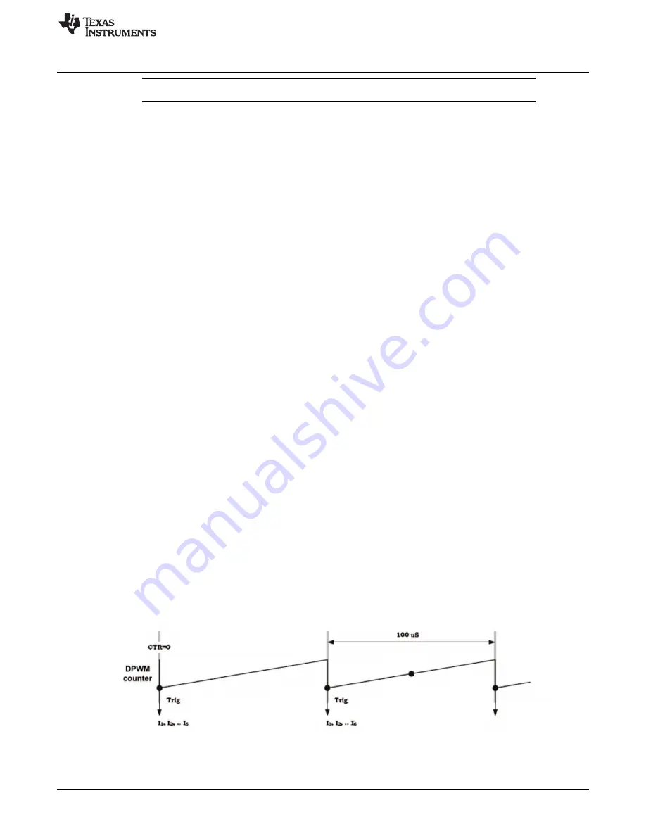
Here the sequencer is synchronized to a DPWM trigger separated in time. This operating mode is nothing
more than the previous example, but with the sequencer allowed to be re-triggered without being reset to
the initial state of seq00.
Requirement: Auto convert 6 currents (I
1
,I
2
,…I
6
) every 100us synchronized to the external trigger.
Figure 8-17.


