Schematics, Bill of Materials, and Layout
www.ti.com
14
SLIU021 – September 2016
Submit Documentation Feedback
Copyright © 2016, Texas Instruments Incorporated
TPS65916 EVM User’s Guide
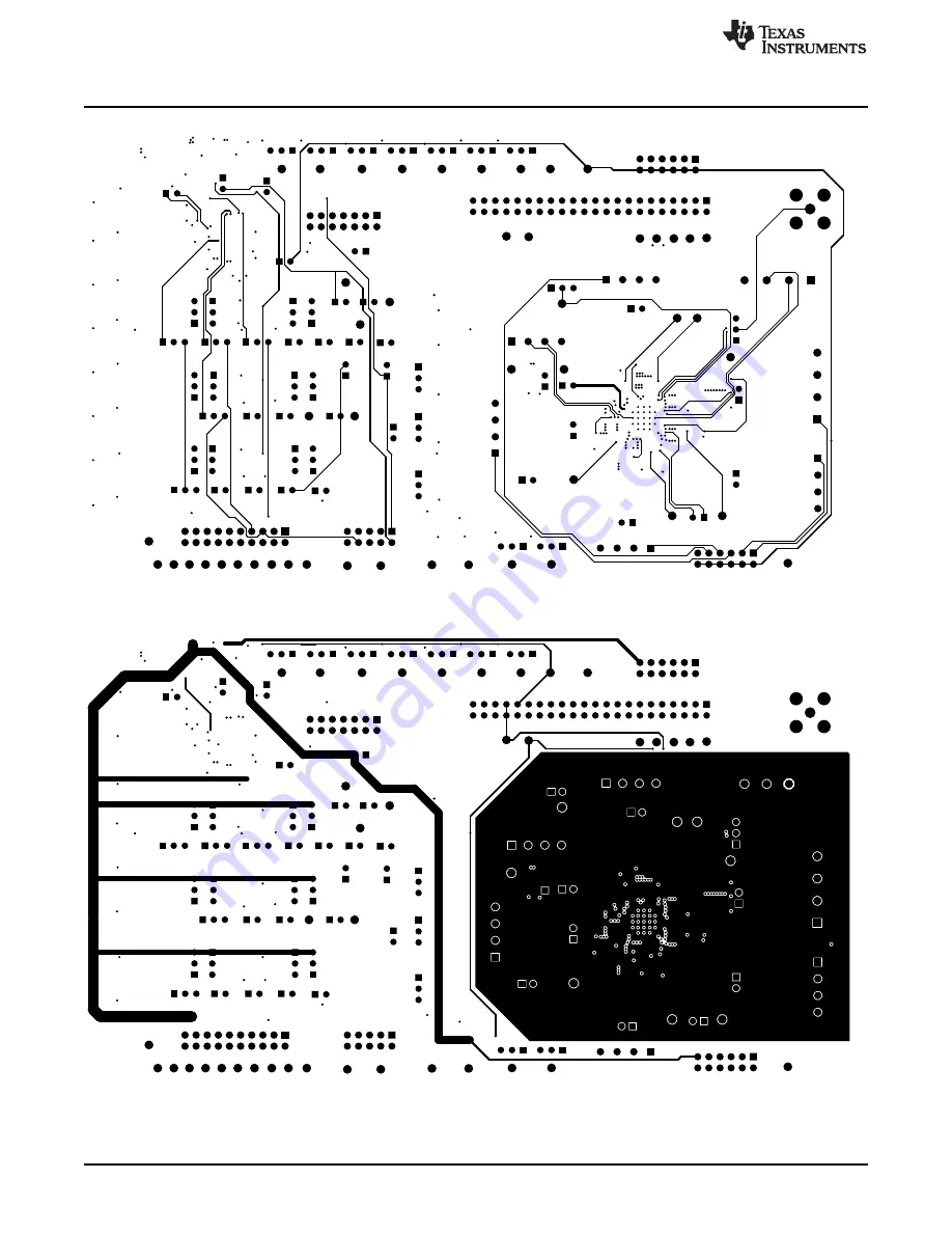
Figure 10. Layer 2 SIGNAL
Figure 11. Layer 3 POWER
Page 1: ...6 EVM Schematic Page 2 6 5 TPS65916 EVM Schematic Page 3 7 6 TPS65916 EVM Schematic Page 4 8 7 Composite Top View 12 8 Top Layer 13 9 Layer 1 GND 13 10 Layer 2 SIGNAL 14 11 Layer 3 POWER 14 12 Bottom...
Page 2: ...Windows to allow access to the registers of the PMIC through USB I2C 1 2 EVM with Components Identified Figure 1 EVM LEDs Display status of POWERGOOD RESET_IN POWER_HOLD LDOVRTC_OUT RESET_OUT INT and...
Page 3: ...through the GUI J26 GPIO_5 Selection GPIO_5 is shorted HIGH to allow the device to power up J30 BOOT Selection BOOT is shorted LOW to exercise the default power up sequence J31 PWRON Selection PWRON i...
Page 4: ...he VIO supply voltage of the PMIC CAUTION It is important to make sure that there is a total of one shunt populated between P12 and P15 If there is a shunt on P12 there should not be one on P15 and vi...
Page 5: ...IN 29 SMPS2_SW 30 SMPS3_FDBK 9 SMPS3_IN 10 SMPS3_SW 11 SMPS4_FDBK 17 SMPS4_IN 18 SMPS4_SW 19 SMPS5_FDBK 45 SMPS5_IN 46 SMPS5_SW 47 SYNCCLKOUT 48 VBG 40 VCCA 42 VCC_SENSE 37 VIO_IN 34 VPROG 20 U1 TPS65...
Page 6: ...DMAE0 35 P2 7 UCB0STE UCA0CLK 36 P3 0 UCB0SIMO UCB0SDA 37 P3 1 UCB0SOMI UCB0SCL 38 P3 2 UCB0CLK UCA0STE 39 P3 3 UCA0TXD UCA0SIMO 40 P3 4 UCA0RXD UCA0SOMI 41 P3 5 TB0 5 42 P3 6 TB0 6 43 P3 7 TB0OUTH SV...
Page 7: ...10 0k R25 10 0k R56 10 0k R24 10 0k R55 10 0k R23 4 1 2 3 P16 4 1 2 3 P5 4 1 2 3 P7 4 1 2 3 P9 4 1 2 3 P11 4 1 2 3 P14 4 1 2 3 P17 1 2 3 J17 1 2 3 J24 1 2 3 J25 1 2 3 J26 1 2 3 J27 1 2 3 J28 1 2 3 J2...
Page 8: ...303 CLEAR H11 SJ 5303 CLEAR H12 SJ 5303 CLEAR Schematics Bill of Materials and Layout www ti com 8 SLIU021 September 2016 Submit Documentation Feedback Copyright 2016 Texas Instruments Incorporated TP...
Page 9: ...J28 J29 J30 J31 J43 J44 J45 J46 J47 J48 J49 J50 J51 J52 J53 J54 JP2 JP3 JP4 JP5 JP6 JP7 31 Header 100mil 3x1 Tin TH Header 3 PIN 100mil Tin PEC03SAAN Sullins Connector Solutions J33 1 Connector TH BNC...
Page 10: ...S Electrocomponents SH 1 SH 2 SH 3 SH 4 SH 5 SH 6 SH 7 SH 8 SH 9 SH 10 SH 11 SH 12 SH 13 SH 14 SH 15 SH 16 SH 17 SH 18 SH 19 SH 20 SH 21 SH 22 SH 23 SH 24 SH 25 SH 26 SH 27 SH 28 28 1x2 Shunt 100mil G...
Page 11: ...7x4 7mm ABLS 24 000MHZ K4F T Abracon Corporation FID1 FID2 FID3 FID4 FID5 FID6 0 Fiducial mark There is nothing to buy or mount Fiducial N A N A L2 0 1uH Inductor Shielded Drum Core Powdered Iron 1 H...
Page 12: ...ocumentation Feedback Copyright 2016 Texas Instruments Incorporated TPS65916 EVM User s Guide 2 3 Layout and Component Placement Figure 7 through Figure 13 show the overviews and layers of the printed...
Page 13: ...m Schematics Bill of Materials and Layout 13 SLIU021 September 2016 Submit Documentation Feedback Copyright 2016 Texas Instruments Incorporated TPS65916 EVM User s Guide Figure 8 Top Layer Figure 9 La...
Page 14: ...l of Materials and Layout www ti com 14 SLIU021 September 2016 Submit Documentation Feedback Copyright 2016 Texas Instruments Incorporated TPS65916 EVM User s Guide Figure 10 Layer 2 SIGNAL Figure 11...
Page 15: ...tics Bill of Materials and Layout 15 SLIU021 September 2016 Submit Documentation Feedback Copyright 2016 Texas Instruments Incorporated TPS65916 EVM User s Guide Figure 12 Bottom Layer Figure 13 Compo...
Page 16: ...ht See Figure 2 3 2 TPS65916EVM Graphical User Interface GUI The GUI for TPS65916EVM gives the user the ability to interact with the internal registers of the device while also allowing control of som...
Page 17: ...where I2 C communication with the device is done This page has four groups blocks of registers Expand each group by clicking the next to the group which lists all the registers in that group Addition...
Page 18: ...n run the commands from the main GUI After each register write or read the script editor records the command that was run When finished recording select Script Stop Recording To save the script on the...
Page 19: ...History 19 SLIU021 September 2016 Submit Documentation Feedback Copyright 2016 Texas Instruments Incorporated Revision History Figure 17 Sample Script Revision History DATE REVISION NOTES September 2...
Page 20: ...ing the warranty period to the address designated by TI and that are determined by TI not to conform to such warranty If TI elects to repair or replace such EVM TI shall have a reasonable time to repa...
Page 21: ...transmitter has been approved by Industry Canada to operate with the antenna types listed in the user guide with the maximum permissible gain and required antenna impedance for each antenna type indic...
Page 22: ...ified allowable ranges some circuit components may have elevated case temperatures These components include but are not limited to linear regulators switching transistors pass transistors current sens...
Page 23: ...REMOVAL OR REINSTALLATION ANCILLARY COSTS TO THE PROCUREMENT OF SUBSTITUTE GOODS OR SERVICES RETESTING OUTSIDE COMPUTER TIME LABOR COSTS LOSS OF GOODWILL LOSS OF PROFITS LOSS OF SAVINGS LOSS OF USE L...
Page 24: ...sponsible for compliance with all legal regulatory and safety related requirements concerning its products and any use of TI components in its applications notwithstanding any applications related inf...