www.ti.com
EVM Assembly Drawings and Layout
Figure 8. TPS6507xEVM Internal 1 (X-Ray View from Top)
17
SLVU291B
–
April 2010
Revised September 2011
TPS6507xEVM
Submit Documentation Feedback
Copyright
©
2010
2011, Texas Instruments Incorporated
Page 1: ...ssembly Drawings and Layout 13 7 Bill of Materials 19 List of Figures 1 TPS6507xEVM Schematic Sheet 1 6 2 TPS6507xEVM Schematic Sheet 2 7 3 TPS6507xEVM Hardware Connection 12 4 TPS6507xEVM Component P...
Page 2: ...regulators LDOs For low noise applications these devices can be forced into fixed frequency PWM using the I2 C interface The I2 C interface allows the user to adjust various settings of the charger t...
Page 3: ...30 MB of free hard disk space 100 MB recommended Minimum of 256 MB of RAM 1 3 3 Power Supply A dc power supply capable of delivering 5 V at 3 A is required to operate this EVM 1 3 4 Ordering Options T...
Page 4: ...chever is less Output Current DCDC1 VIN Min to max 600 mA DCDC2 DEFDCDC2 Low 1 8 V TPS65070 VOUT_DCDC2 DEFDCDC2 TPS650732 3 3 V High DEFDCDC2 Low 1 8 V Default Output Voltage VOUT_DCDC2 TPS65072 DEFDC...
Page 5: ...LSB Sampling rime 220 s Conversion time 19 s Reference voltage on 1 2 26 1 BYPASS Power Path Minimum battery voltage VBATMIN 2 75 V Input overvoltage protection V OVP 5 8 6 0 6 3 V Switching from AC t...
Page 6: ...70EVM 430 schematic NOTE These diagrams are provided for reference only See Table 3 the Bill of Materials for specific component values Figure 1 TPS6507xEVM Schematic Sheet 1 6 TPS6507xEVM SLVU291B Ap...
Page 7: ...i com TPS6507xEVM Schematic Figure 2 TPS6507xEVM Schematic Sheet 2 7 SLVU291B April 2010 Revised September 2011 TPS6507xEVM Submit Documentation Feedback Copyright 2010 2011 Texas Instruments Incorpor...
Page 8: ...Register PPATH1 01h The default input current limit is set to 500 mA For more information refer to the respective device data sheet available for download at www ti com 4 1 4 J4 SYS J4 is connected to...
Page 9: ...urrent and default output voltage of DCDC2 4 1 11 J11 VDCDC3 GND J11 pins 3 and 4 are the positive output of the step down converter DCDC3 J11 pins 1 and 2 are the GND connection of DCDC3 A load can b...
Page 10: ...cted to the open drain output PGOOD PGOOD goes low depending on the setting in the PGOODMASK register In this register different PGOOD bits of each dc dc converter and LDO can be connected to the PGOO...
Page 11: ...rters and LDOs that are part of the internal automatic sequence should be terminated to GND To control the converters with the respective individual ENABLE pins the power sequence for the dc dc conver...
Page 12: ...6507x product folder on the TI web site www ti com Download the software and execute it follow the on screen instructions to complete the installation 5 2 Hardware Setup Figure 3 shows a typical hardw...
Page 13: ...CB with all components in an active area on the top side of the board NOTE Board layouts are not to scale These figures are intended to show how the board is laid out they are not intended to be used...
Page 14: ...S EVM Assembly Drawings and Layout www ti com Figure 5 TPS6507xEVM Silkscreen Viewed from Top 14 TPS6507xEVM SLVU291B April 2010 Revised September 2011 Submit Documentation Feedback Copyright 2010 201...
Page 15: ...Assembly Drawings and Layout Figure 6 TPS6507xEVM Top Copper Viewed from Top 15 SLVU291B April 2010 Revised September 2011 TPS6507xEVM Submit Documentation Feedback Copyright 2010 2011 Texas Instrumen...
Page 16: ...gs and Layout www ti com Figure 7 TPS6507xEVM Bottom Copper X Ray View from Top 16 TPS6507xEVM SLVU291B April 2010 Revised September 2011 Submit Documentation Feedback Copyright 2010 2011 Texas Instru...
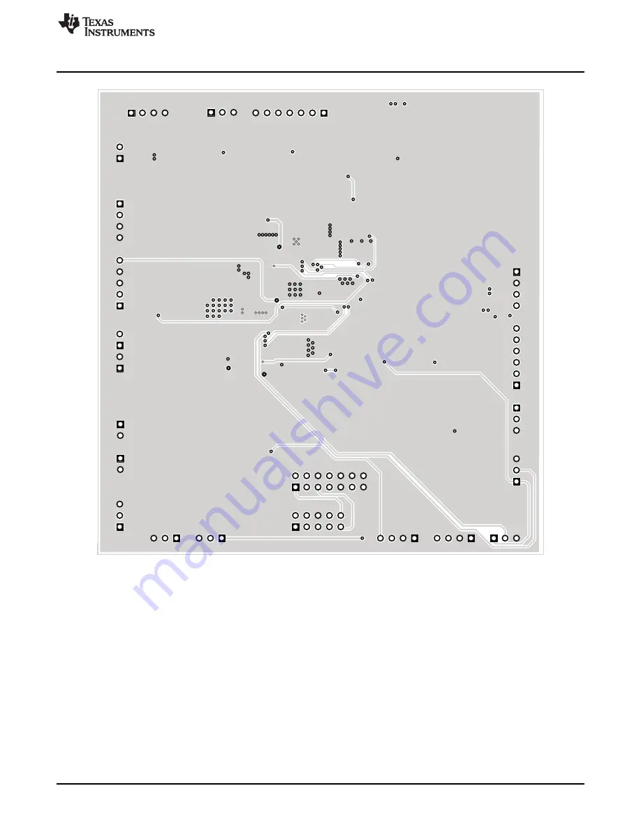
Page 17: ...sembly Drawings and Layout Figure 8 TPS6507xEVM Internal 1 X Ray View from Top 17 SLVU291B April 2010 Revised September 2011 TPS6507xEVM Submit Documentation Feedback Copyright 2010 2011 Texas Instrum...
Page 18: ...ings and Layout www ti com Figure 9 TPS6507xEVM Internal 2 X Ray View from Top 18 TPS6507xEVM SLVU291B April 2010 Revised September 2011 Submit Documentation Feedback Copyright 2010 2011 Texas Instrum...
Page 19: ...0 mA 0 118 x 16 16 16 16 16 Q65110A1931 Q65110A1931 Osram D10 D11 Common Anode 0 134 inch D12 D13 D14 D15 D16 D17 Inductor SMT 0 153 x 1 1 1 1 1 L1 47 H LPS4018 473MLB Coilcraft 0 56 A 650 m 0 153 inc...
Page 20: ...Systems IC Power Solution for 0 1 0 0 0 TPS65072RSL TPS65072RSL TI Navigation Systems IC Power Solution for 0 0 1 0 0 TPS65073RSL TPS65073RSL TI Navigation Systems IC Power Solution for 0 0 0 1 0 TPS6...
Page 21: ...uct This notice contains important safety information about temperatures and voltages For additional information on TI s environmental and or safety programs please contact the TI application engineer...
Page 22: ...for use in safety critical applications such as life support where a failure of the TI product would reasonably be expected to cause severe personal injury or death unless officers of the parties have...
Page 23: ...user Electronics Authorized Distributor Click to View Pricing Inventory Delivery Lifecycle Information Texas Instruments TPS65070EVM 430 TPS65072EVM 430 TPS650731EVM 430 TPS650732EVM 430 TPS65073EVM 4...