


Start
Tsamp1
A ADINx
Sample time in normal operation mode
Sample time doubled in self-test mode
Conversion of last value sampled
AD_Core _In
AD
REFHI
AD
REFLO
A ADINx
time
Ext. Input
discharge of ext. cap
charging of ext. cap
Tsamp2
Basic Operation
876
SPNU563A – March 2018
Copyright © 2018, Texas Instruments Incorporated
Analog To Digital Converter (ADC) Module
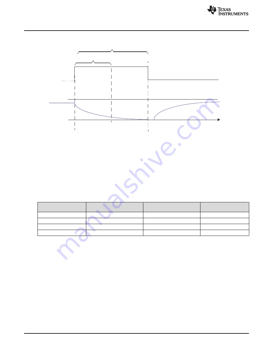
Figure 22-16. Timing for Self-Test Mode
22.2.6.2.1 Use of Self-Test Mode to Determine Open/Short on ADC Input Channels
The following sequence needs to be used to deduce the ADC pin status:
•
Convert the channel with self test enabled and with the reference voltage as Vreflo. Store the
conversion result, say Vd.
•
Convert the channel with self test enabled and with the reference voltage as Vrefhi. Store the
conversion result, say Vu.
•
Convert the channel with self test disabled. Store the conversion result, say Vn.
The results can be interpreted using the following table.
Table 22-4. Determination of ADC Input Channel Condition
Normal Conversion
Result, Vn
Self-test Conversion
Result, Vu
Self-test Conversion
Result, Vd
Pin Condition
Vn
Vn < Vu < AD
REFHI
AD
REFLO
< Vd < Vn
Good
AD
REFHI
AD
REFHI
approx. AD
REFHI
Shorted to AD
REFHI
AD
REFLO
approx. AD
REFLO
AD
REFLO
Shorted to AD
REFLO
Unknown
AD
REFHI
AD
REFLO
Open
22.2.6.3 ADC Power-Down Mode
This is an inactive mode in which the clocks to the ADC module are stopped leaving the module in a static
state. The clock to the ADC core (ADCLK) is stopped whenever there are no ongoing conversions. This is
the clock-gating implementation requirement. Also, the ADC module places the ADC core into the power
down mode such that there is minimal current drawn from the ADC operating and reference supplies.
22.2.6.3.1 Powering Down Just The ADC Core
The ADC core can be individually powered down without stopping the clocks to the ADC module. This can
be done by setting the POWERDOWN bit of the ADC Operating Mode Control Register
(ADOPMODECR.3). Whenever a conversion is required the POWERDOWN bit must be cleared, and a
minimum time
t
d(PU-ADV)
,
(see the specific device data sheet for actual value) has to be allowed before
starting a new conversion. This wait must be implemented in the application software.


