background image

Audio Processing Features

Stereo/Mono Mode 

Selection

Input Mixing and DC 

Block Filter Options

Volume and 

Pre/Post Scaling 

Controls

Audio I/O Information 

and Shortcut

Master Volume 

Shortcut

Audio Player 

Controls

Snapshot 

Feature

Configuration

I²C Monitor Shortcut

Device Connection 

Status

Block Diagram

www.ti.com

Using the TAS5733LEVM with PurePath Console 3

7

SLOU439 – March 2016

Submit Documentation Feedback

Copyright © 2016, Texas Instruments Incorporated

TAS5733L Evaluation Module

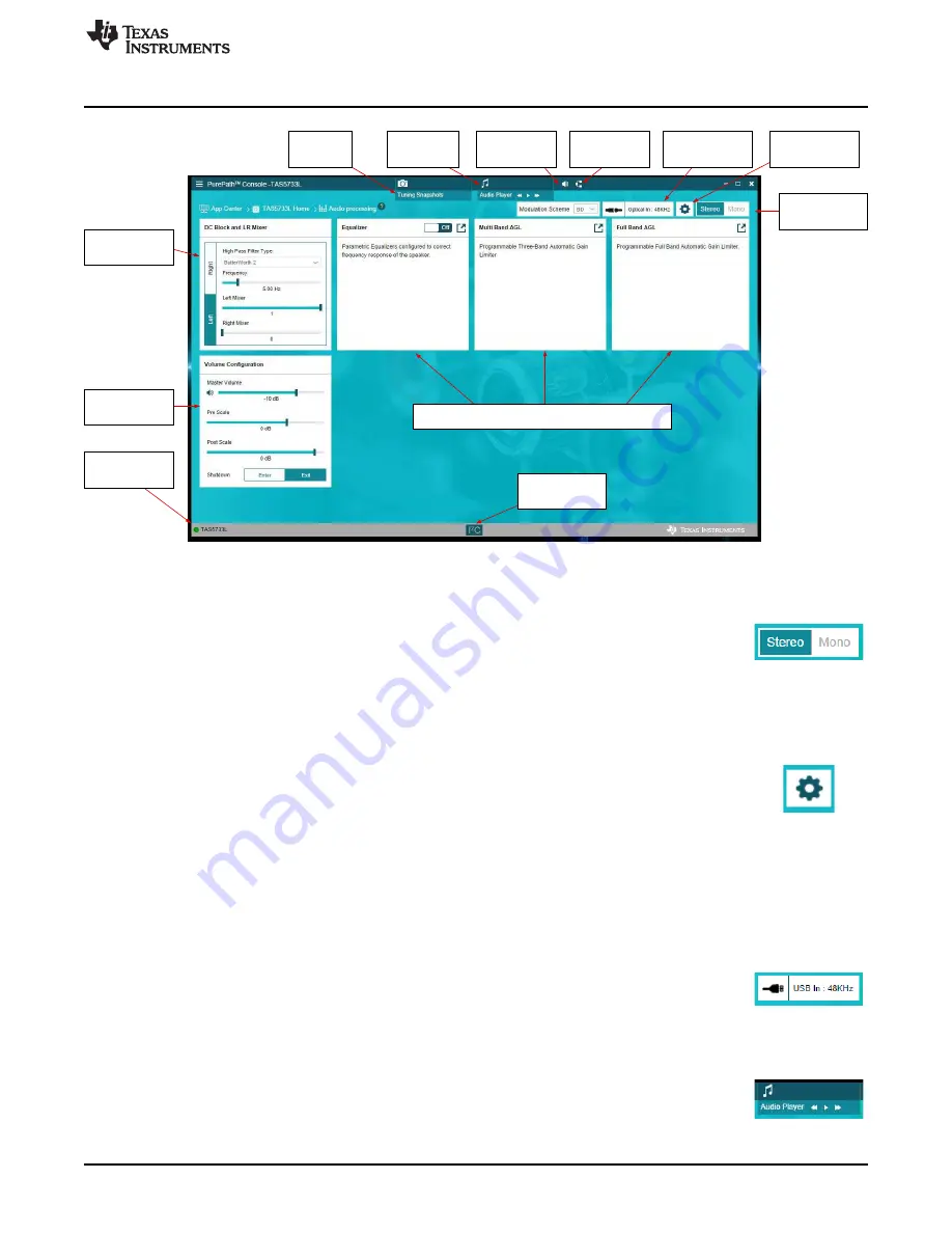
Figure 5. TAS5733LEVM Audio Processing Windows

Stereo/Mono device selection

Configure each device of the EVM individually by selecting between

Stereo

and

Mono

on the upper right section of the

Audio Processing

window. The configuration of each

device is made with the same controls; the only difference is that when configuring the
mono device, the channel (left or right) driving the power stage is selected. Detailed
information is found in the

Configuration

section.

Configuration

Access the configuration menu by clicking in the gear icon next to the

Stereo/Mono

selection

button. In Stereo mode, only the option to reset the tuning done in the GUI

is offered, in mono mode, the user can select also if the left or right channel from the
digital audio processor drives the power stage of the amplifier. When performing the
Reset tuning function, the devices are configured with the default settings. By default,
both devices are configured with a master volume gain of –10 dB, multiband AGLs are
set to 0 dB while full band AGL is set to –1 dB. Stereo device equalizers are turned off,
but mono device has a default-configured 120-Hz low-pass filter for use in subwoofer
applications. The left channel of the mono device is driving the power stage by default.

Audio I/O shortcut

This section shows the audio source and sampling frequency that is used to generate
the I²S input for the TAS5733L amplifiers. The user is redirected to the main Audio I/O
window after clicking this button.

Audio Player

The Audio Player is used to play audio tracks available in the PC and perform various
tuning operations. Clicking on the Audio Player launches a floating window, where
audio tracks are added or played.

Summary of Contents for TAS5733L

Page 1: ...his document the abbreviation EVM and the term evaluation module are synonymous with the TAS5733LEVM evaluation module unless otherwise noted space space Contents 1 Overview 2 2 EVM Setup 3 3 Using th...

Page 2: ...ier with audio processing features The EVM is configured in Two Device 2 1 mode with one stereo device using bridge tied load for left and right channels and one mono device configured for mono applic...

Page 3: ...available through PPCMB 2 EVM Setup Figure 2 illustrates the EVM setup Figure 2 Evaluation Module and PurePath Console Motherboard Connection 2 1 Requirements The following are required to operate and...

Page 4: ...the PPCMB this is not necessary if the source is USB audio Connect the speakers to the outputs of the EVM 3 Using the TAS5733LEVM with PurePath Console 3 3 1 TAS5733L Application Connection The TAS573...

Page 5: ...ctions in the page by clicking on the left or right arrows Figure 4 TAS5733L Application Home Window 3 3 Hardware Checks The following window verifies the correct connection of the evaluation module c...

Page 6: ...Input Sampling rates available USB in 48 kHz Optical In 48 kHz 44 1 kHz Coax In 48 kHz 44 1 kHz Although PPCMB operating range is up to 192 kHz the available sample rates are limited to theTAS5733L 3...

Page 7: ...ion menu by clicking in the gear icon next to the Stereo Mono selection button In Stereo mode only the option to reset the tuning done in the GUI is offered in mono mode the user can select also if th...

Page 8: ...I C Monitor by clicking the I C Monitor icon in the bottom bar in any of the pages Equalizer The Equalizer window allows the configuration and setting of the different Biquads available in the audio...

Page 9: ...12 V PVDD 4 load The filters used for the multiband AGL crossover are configured according to the specific need By default the three band crossover frequencies are set to 300 Hz and 3 kHz using secon...

Page 10: ...ifferent configuration for left and right channels for the stereo device An Input Output chart is available to easily configure the threshold levels for each band Drag and select each threshold and fi...

Page 11: ...ted to the selected device that is stereo or mono Manual changes to the register values is accomplished by double clicking in the desired bit to change Clicking on Read All Registers allows monitoring...

Page 12: ...on is enabled The log tab has different options sp Search search for a particular command Save to a file saves the log as a config file to the PC Delete Output clears the log history Copy to a Clipboa...

Page 13: ...tion modes for the device in the end system In order to achieve this first select the desired snapshot then go to the End System Integration window and generate the configuration file In System Debugg...

Page 14: ...he right side of the board used for the connection of the speakers and loads that are used together with the EVM These connectors correspond to left and right channel of the stereo device and the sing...

Page 15: ...ate the devices in AD mode by populating the optional AD capacitors C24 C27 and C51 in the evaluation module The I C address of the devices can be changed as well if required By default the stereo dev...

Page 16: ...439 March 2016 Submit Documentation Feedback Copyright 2016 Texas Instruments Incorporated TAS5733L Evaluation Module 4 1 TAS5733LEVM Board Layout Figure 13 through Figure 18 show the PCB layouts Figu...

Page 17: ...ill of Materials and Schematic 17 SLOU439 March 2016 Submit Documentation Feedback Copyright 2016 Texas Instruments Incorporated TAS5733L Evaluation Module Figure 15 TAS5733LEVM Ground Layer Figure 16...

Page 18: ...als and Schematic www ti com 18 SLOU439 March 2016 Submit Documentation Feedback Copyright 2016 Texas Instruments Incorporated TAS5733L Evaluation Module Figure 17 TAS5733LEVM Bottom Layer Figure 18 T...

Page 19: ...KA88L Murata CAP CERM 0 68 F 50 V 10 X7R 1206 1206 13 C28 C29 2 390uF UCL1V391MNL1GS Nichicon CAP AL 390 F 35 V 20 0 08 ohm SMD 10x10 14 C58 1 0 1uF C1005X7R1H104K050BB TDK CAP CERM 0 1uF 50V 10 X7R 0...

Page 20: ...C52 C53 C54 C55 C56 C57 0 330pF GRM1885C1H331JA01D Murata CAP CERM 330 pF 50 V 5 C0G NP0 0603 0603 31 FID1 FID2 FID3 FID4 FID5 FID6 0 N A N A Fiducial mark There is nothing to buy or mount Fiducial 3...

Page 21: ...68 F C25 0 68 F C26 PVDD BTL_L GND J1 OUT GND 0 68 F C22 0 68 F C23 GND GND GND OUTA1 OUTD1 MCLK GND GND GND 3 3V 4700pF C15 GND 0 047 F C14 4700pF C13 470 R1 4 7 F C9 0 1 F C10 1 F C12 0 1 F C11 GND...

Page 22: ...ard 18 0k R7 GND GND ADR2 FAULT PDN RST MCLK SCLK LRCLK SDIN 0 01 F C46 0 01 F C47 GND 0 68 F C49 GND 0 68 F C50 PBTL PBTL OUTAB OUTCD 3 3V LRCLK SCLK SDIN SCL SDA RST GND MCLK GND GND GND 3 3V 0 047...

Page 23: ...41 42 43 44 45 46 47 48 49 50 J4A GND 105 GND 106 GND 107 GND 108 51 52 53 54 55 56 57 58 59 60 61 62 63 64 65 66 67 68 69 70 71 72 73 74 75 76 77 78 79 80 81 82 83 84 85 86 87 88 89 90 91 92 93 94 95...

Page 24: ...ing the warranty period to the address designated by TI and that are determined by TI not to conform to such warranty If TI elects to repair or replace such EVM TI shall have a reasonable time to repa...

Page 25: ...transmitter has been approved by Industry Canada to operate with the antenna types listed in the user guide with the maximum permissible gain and required antenna impedance for each antenna type indic...

Page 26: ...ified allowable ranges some circuit components may have elevated case temperatures These components include but are not limited to linear regulators switching transistors pass transistors current sens...

Page 27: ...REMOVAL OR REINSTALLATION ANCILLARY COSTS TO THE PROCUREMENT OF SUBSTITUTE GOODS OR SERVICES RETESTING OUTSIDE COMPUTER TIME LABOR COSTS LOSS OF GOODWILL LOSS OF PROFITS LOSS OF SAVINGS LOSS OF USE L...

Page 28: ...sponsible for compliance with all legal regulatory and safety related requirements concerning its products and any use of TI components in its applications notwithstanding any applications related inf...

Page 29: ...Mouser Electronics Authorized Distributor Click to View Pricing Inventory Delivery Lifecycle Information Texas Instruments TAS5733LEVM...

Reviews: