www.ti.com
Board Layout
9
SNVU579 – September 2017
Submit Documentation Feedback
Copyright © 2017, Texas Instruments Incorporated
LM73605 / LM73606 EVM User’s Guide
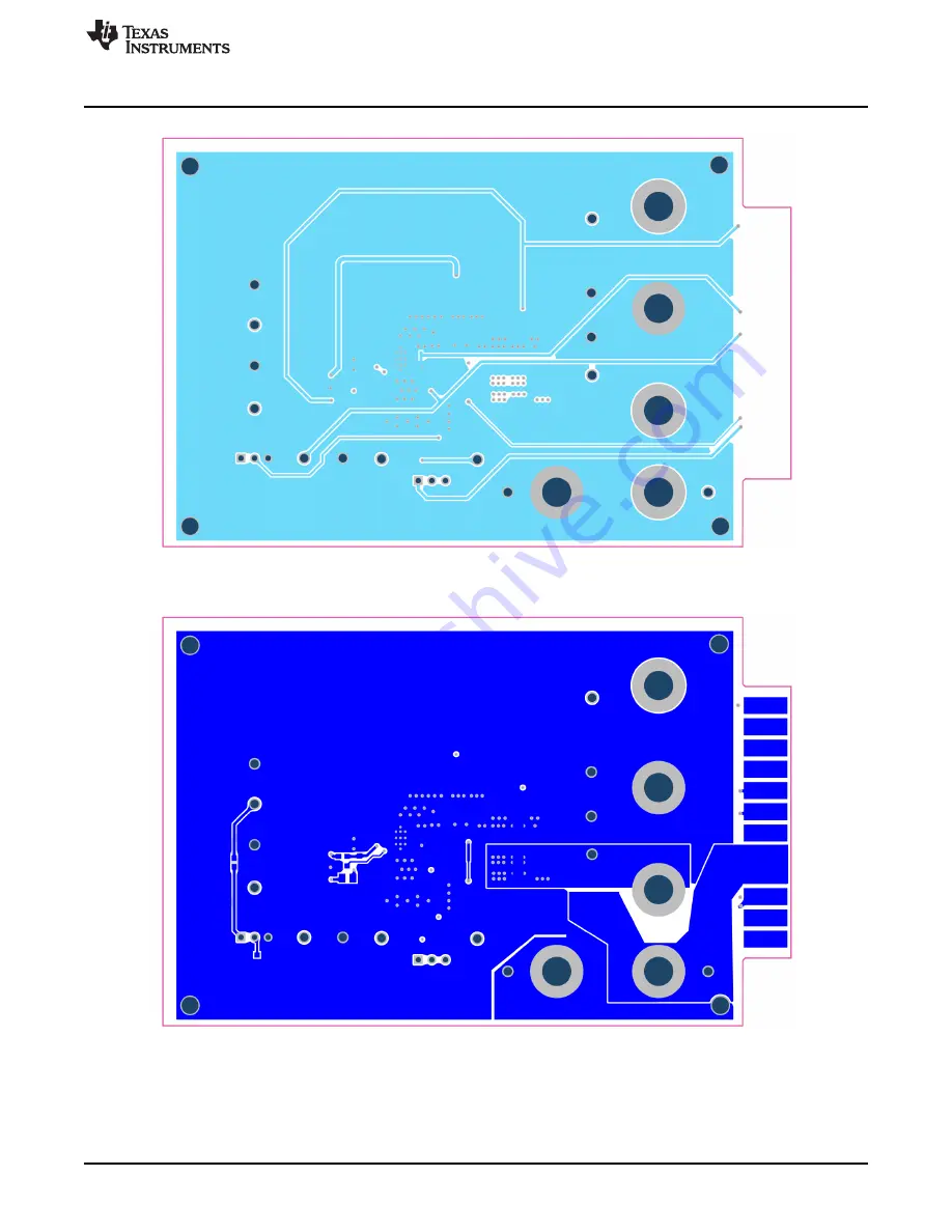
Figure 8. Mid-Layer 2 Routing
Figure 9. Bottom Layer Routing
Page 1: ...tage and up to 5 A LM73605 or 6 A LM73606 load current with exceptional efficiency and output accuracy in a very small solution size The EVM provides multiple power connectors and test points as well as mode setting options and enable input options for customer convenience It also provides a good layout example which is optimized for EMI performance and thermal performance Table 1 Device and Packa...
Page 2: ...ide range of applications Automatic frequency foldback at light load and optional external bias improve efficiency over the entire load range The family requires few external components and has a pinout designed for simple PCB layout with optimal EMI and thermal performance Protection features include thermal shutdown input undervoltage lockout cycle by cycle current limiting and hiccup short circ...
Page 3: ...r between VOUT and PGND connectors using short and thick wires 3 Set the supply voltage VIN at an appropriate level between 6 V to 36 V Set the current limit of the supply to an appropriate level as well 4 Turn on the power supply With the default configuration the EVM should power up and provide VOUT 5 V 5 Monitor the output voltage The maximum load current should be 5 A with LM73605 or 6 A with ...
Page 4: ...I Input voltage to input filter of the converter If the input filter is desired between the supply voltage and the LM73605 6 connect the supply voltage between VIN EMI and GND EMI The supply voltage should be connected to the board with short and thick wires to handle pulsing input current GND EMI Ground connection near the input filter This is the current return path for the supply connected to V...
Page 5: ...cted together and the device will operate in auto mode at light loads With auto mode discontinuous conduction mode DCM and pulse frequency modulation PFM mode are employed at light loads to provide high efficiency PFM mode also provides very low quiescent current at no load At heavier load when inductor current is in DCM or continuous conduction mode CCM operation the switching frequency is determ...
Page 6: ...xas Instruments Incorporated LM73605 LM73606 EVM User s Guide 4 Schematic The three variants of the EVM shown in Table 2 share the same schematic with component variants shown in Section 6 The LM73605EVM_5V_400K Schematic is shown in Figure 4 as an example Figure 4 LM73605EVM_5V_400K Schematic ...
Page 7: ... package offers an exposed thermal pad which must be soldered to the copper landing on the PCB for optimal thermal performance The PCB consists of a 4 layer design There are 2 oz copper planes on the top and bottom and 1 oz copper mid layer planes to dissipate heat with an array of thermal vias under the thermal pad to connect to all four layers Test points have been provided for ease of use to co...
Page 8: ...yout www ti com 8 SNVU579 September 2017 Submit Documentation Feedback Copyright 2017 Texas Instruments Incorporated LM73605 LM73606 EVM User s Guide Figure 6 Top Layer Routing Figure 7 Mid Layer 1 Ground Plane ...
Page 9: ...com Board Layout 9 SNVU579 September 2017 Submit Documentation Feedback Copyright 2017 Texas Instruments Incorporated LM73605 LM73606 EVM User s Guide Figure 8 Mid Layer 2 Routing Figure 9 Bottom Layer Routing ...
Page 10: ...CW0603100KFKEA 2 R3 RBIAS RES 0 5 0 1 W 0603 Vishay Dale CRCW06030000Z0EA 1 R4 RFBB RES 24 9 k 1 0 1 W 0603 Vishay Dale CRCW060324K9FKEA 1 R6 RT RES 17 8 k 1 0 1 W 0603 Vishay Dale CRCW060317K8FKEA 1 R8 RENT RES 200 k 1 0 125 W 0805 Vishay Dale CRCW0805200KFKEA 1 R9 RENB RES 121 k 1 0 125 W 0805 Vishay Dale CRCW0805121KFKEA 1 R10 RPU RES 10 0 k 1 0 1 W 0603 Vishay Dale CRCW060310K0FKEA 1 U1 LM7360...
Page 11: ...W 0603 Vishay Dale CRCW0603100KFKEA 3 R3 RBIAS RES 0 5 0 1 W 0603 Vishay Dale CRCW06030000Z0EA 1 R4 RFBB RES 24 9 k 1 0 1 W 0603 Vishay Dale CRCW060324K9FKEA 1 R8 RENT RES 200 k 1 0 125 W 0805 Vishay Dale CRCW0805200KFKEA 1 R9 RENB RES 121 k 1 0 125 W 0805 Vishay Dale CRCW0805121KFKEA 1 R10 RPU RES 10 0 k 1 0 1 W 0603 Vishay Dale CRCW060310K0FKEA 1 U1 LM73605RNPR 3 5V to 36V 5A Synchronous Step Do...
Page 12: ...W 0603 Vishay Dale CRCW0603100KFKEA 3 R3 RBIAS RES 0 5 0 1 W 0603 Vishay Dale CRCW06030000Z0EA 1 R4 RFBB RES 24 9 k 1 0 1 W 0603 Vishay Dale CRCW060324K9FKEA 1 R8 RENT RES 200 k 1 0 125 W 0805 Vishay Dale CRCW0805200KFKEA 1 R9 RENB RES 121 k 1 0 125 W 0805 Vishay Dale CRCW0805121KFKEA 1 R10 RPU RES 10 0 k 1 0 1 W 0603 Vishay Dale CRCW060310K0FKEA 1 U1 LM73606RNPR 3 5V to 36V 5A Synchronous Step Do...
Page 13: ...6 1 2 1 8 2 4 3 3 6 4 2 4 8 5 4 6 50 55 60 65 70 75 80 85 90 95 100 EFF_ VIN 12 V VIN 24 V www ti com Performance Curves 13 SNVU579 September 2017 Submit Documentation Feedback Copyright 2017 Texas Instruments Incorporated LM73605 LM73606 EVM User s Guide 7 Performance Curves 7 1 LM73605EVM 5V 2MHz 5 A 2 2 MHz Board Curves Figure 10 LM73605 5 V 2 2 MHz Efficiency in Auto Mode Figure 11 LM73605 5 V...
Page 14: ...iency 0 0 6 1 2 1 8 2 4 3 3 6 4 2 4 8 5 4 6 50 55 60 65 70 75 80 85 90 95 100 EFF_ VIN 12 V VIN 24 V Performance Curves www ti com 14 SNVU579 September 2017 Submit Documentation Feedback Copyright 2017 Texas Instruments Incorporated LM73605 LM73606 EVM User s Guide 7 2 LM73605EVM 5V 400K 5 A 400 kHz Board Curves Figure 16 LM73605 5 V 400 kHz Efficiency in Auto Mode Figure 17 LM73605 5 V 400 kHz Ef...
Page 15: ...iency 0 0 6 1 2 1 8 2 4 3 3 6 4 2 4 8 5 4 6 50 55 60 65 70 75 80 85 90 95 100 EFF_ VIN 12 V VIN 24 V www ti com Performance Curves 15 SNVU579 September 2017 Submit Documentation Feedback Copyright 2017 Texas Instruments Incorporated LM73605 LM73606 EVM User s Guide 7 3 LM73606EVM 5V 400K 6 A 400 kHz Board Curves Figure 22 LM73606 5 V 400 kHz Efficiency in Auto Mode Figure 23 LM73606 5 V 400 kHz Ef...
Page 16: ... were obtained in TI labs for reference only The radiated EMI test was performed in a 3 meter standard lab The input filter values used for this test is shown in Table 6 The input filter consists of C FLTs L IN and CBULK located on the bottom side of the PCB Note that the input filter components are not mounted on the PCB by default Table 6 EMI Filter Component Values Component C FLTs L IN CBULK V...
Page 17: ...y set forth above or credit User s account for such EVM TI s liability under this warranty shall be limited to EVMs that are returned during the warranty period to the address designated by TI and that are determined by TI not to conform to such warranty If TI elects to repair or replace such EVM TI shall have a reasonable time to repair such EVM or provide replacements Repaired EVMs shall be warr...
Page 18: ...the user guide with the maximum permissible gain and required antenna impedance for each antenna type indicated Antenna types not included in this list having a gain greater than the maximum gain indicated for that type are strictly prohibited for use with this device Concernant les EVMs avec antennes détachables Conformément à la réglementation d Industrie Canada le présent émetteur radio peut fo...
Page 19: ...ed loads Any loads applied outside of the specified output range may also result in unintended and or inaccurate operation and or possible permanent damage to the EVM and or interface electronics Please consult the EVM user guide prior to connecting any load to the EVM output If there is uncertainty as to the load specification please contact a TI field representative During normal operation even ...
Page 20: ...COST OF REMOVAL OR REINSTALLATION ANCILLARY COSTS TO THE PROCUREMENT OF SUBSTITUTE GOODS OR SERVICES RETESTING OUTSIDE COMPUTER TIME LABOR COSTS LOSS OF GOODWILL LOSS OF PROFITS LOSS OF SAVINGS LOSS OF USE LOSS OF DATA OR BUSINESS INTERRUPTION NO CLAIM SUIT OR ACTION SHALL BE BROUGHT AGAINST TI MORE THAN TWELVE 12 MONTHS AFTER THE EVENT THAT GAVE RISE TO THE CAUSE OF ACTION HAS OCCURRED 8 2 Specif...
Page 21: ... TI Resource NO OTHER LICENSE EXPRESS OR IMPLIED BY ESTOPPEL OR OTHERWISE TO ANY OTHER TI INTELLECTUAL PROPERTY RIGHT AND NO LICENSE TO ANY TECHNOLOGY OR INTELLECTUAL PROPERTY RIGHT OF TI OR ANY THIRD PARTY IS GRANTED HEREIN including but not limited to any patent right copyright mask work right or other intellectual property right relating to any combination machine or process in which TI product...
Page 22: ...Mouser Electronics Authorized Distributor Click to View Pricing Inventory Delivery Lifecycle Information Texas Instruments LM73605EVM 5V 2MHZ LM73605EVM 5V 400K LM73606EVM 5V 400K ...