background image

LDC1312/1612 EVM Schematics and Layout

www.ti.com

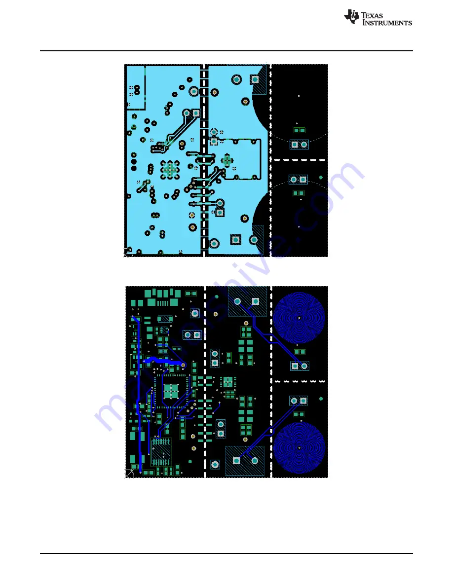
Figure 31. LDC1312/1612 Layout MidLayer 2 – Signals and Power Plane

Figure 32. LDC1312/1612 Layout Bottom Layer – Signals Plane

22

LDC131x and LDC161x EVM User’s Guide

SNOU133 – December 2014

Submit Documentation Feedback

Copyright © 2014, Texas Instruments Incorporated

Summary of Contents for LDC131 Series

Page 1: ...LDC131x and LDC161x EVM User s Guide User s Guide Literature Number SNOU133 December 2014 ...

Page 2: ...n Tab 10 3 8 Registers Tab 11 3 9 Error Tab 12 3 10 Data Streaming 13 3 10 1 Average Point Min Max Values 13 3 10 2 Zooming and Scaling 13 3 10 3 Frequency Count 14 3 11 Saving and Loading 14 3 11 1 Configurations 14 3 11 2 Plot Data 14 3 11 3 Data Logging 15 3 12 Input Clock Options 15 3 13 Using Multiple EVMs Simultaneously 15 3 14 EVM Sensors 16 4 LDC1312 1612 EVM Schematics and Layout 18 5 LDC...

Page 3: ...pacitor Setting 17 24 LDC1312 1612 USB Connection 18 25 LDC1312 1612 Power Circuit 18 26 LDC1312 1612 Clocking 19 27 LDC1312 1612 19 28 LDC1312 1612 MSP430 Connections 20 29 LDC1312 1612 Layout Top Layer Signals and Components 21 30 LDC1312 1612 Layout MidLayer 1 Ground Plane 21 31 LDC1312 1612 Layout MidLayer 2 Signals and Power Plane 22 32 LDC1312 1612 Layout Bottom Layer Signals Plane 22 33 LDC...

Page 4: ...scription 13 3 Zooming and Scaling Options 13 4 BOM for LDC1312 EVM 28 5 BOM for LDC1612 EVM 30 6 BOM for LDC1314 EVM 32 7 BOM for LDC1614 EVM 34 4 List of Tables SNOU133 December 2014 Submit Documentation Feedback Copyright 2014 Texas Instruments Incorporated ...

Page 5: ...es to a host computer Figure 1 LDC1312 1612 Evaluation Module The LDC1312 1612 EVM includes two example PCB sensors which are PCB inductors with 330 pF 1 COG NP0 capacitors connected in parallel to form an LC tank LDC1314 1614 includes two additional spaces to which two sensors can be connected When the evaluation module first powers up from the USB port it will flash a series of green and red LED...

Page 6: ...er Interface GUI software Figure 3 System Level Diagram of EVM 2 1 1 Set Up Requirements The LDC131x 161x GUI and drivers must be installed on the host Driver installation will launch automatically once the device is plugged in See Section 3 3 for more information on software installation 2 1 2 Loading and Running 1 Plug the EVM into the host computer The host computer should automatically detect ...

Page 7: ...Go back to the Streaming tab Figure 5 Configuration Registers 5 Select Start in order to begin streaming the data Figure 6 Start Streaming 6 The data will update in the graph shown in Figure 7 Zoom into each tab if needed by right clicking on it and selecting Zoom to Figure 7 Streaming Data from Two Channels 7 SNOU133 December 2014 LDC131x and LDC161x EVM User s Guide Submit Documentation Feedback...

Page 8: ...VM for the GUI The GUI must be installed on the host The EVM driver must be installed on the host The EVM must be connected to a full speed USB port USB 1 0 or above 3 3 Installation Process The EVM GUI can be downloaded from the TI website Select LDC131x 161x SW for software installation 3 4 Reconnecting the EVM If the EVM is disconnected from the host at any time simply reconnect the device and ...

Page 9: ...ted to Connection State the PC and if so provides details of the EVM is disconnected connected EVM Opens saved register settings and Open defaults Saves all current register settings and Save defaults Register Settings Show LDC131x 161x Register Settings Configuration Show EVM Configuration Streaming Show Streaming Section Error Window Show Error Section 9 SNOU133 December 2014 LDC131x and LDC161x...

Page 10: ...ange Changes are applied immediately Press Read All to refresh all configuration status and data settings Press Restore from Defaults to write values from the default column if they exist to the current register values Press Save Values as Defaults to restore the current configuration to the default settings Figure 10 Reading and Setting Values 10 LDC131x and LDC161x EVM User s Guide SNOU133 Decem...

Page 11: ...uble click on a register in the table to read write If a register is read only the selected register is read immediately and the table value updated If the register is read write a dialog pops up and the user can set a new register value If the value is not changed it will default to a read Figure 12 Read Write Register Dialog Press Save Values as Default to save all configuration status and data ...

Page 12: ...are highlighted in red Green area indicates no errors were detected Figure 13 Error Tab Ensure that errors are reported by selecting Unmask the error in the configuration tab Figure 14 Error Configuration 12 LDC131x and LDC161x EVM User s Guide SNOU133 December 2014 Submit Documentation Feedback Copyright 2014 Texas Instruments Incorporated ...

Page 13: ... data points currently in the plot Point Mode The newest data point value currently in the plot Min Mode The minimum data point value currently in the plot Max Mode The maximum data point value currently in the plot Standard Dev The standard deviation of the data currently in the plot A larger number of samples results in a larger averaging window 3 10 2 Zooming and Scaling Plots are interactive Z...

Page 14: ...ype a name for the file Figure 17 Save Icon Configurations include all register names current values and default values They are saved in Comma Separated Files csv and can be modified using a text or spreadsheet editor To load a configuration click on the Open icon in the toolbar and select the configuration file Figure 18 Open Icon 3 11 2 Plot Data Right click a plot and select Save Data Data can...

Page 15: ...g Data button a second time 3 12 Input Clock Options By default the input clock for LDC131x 161x is generated externally by PLL clock synchronizer and has a value of 40 MHz It is possible to remove R11 and connect an external clock by populating J2 3 13 Using Multiple EVMs Simultaneously To connect multiple EVMs to a single host multiple instances of the GUI should be launched Each EVM will interf...

Page 16: ... LC tanks The EVM includes two 2 layer 32 turn 14mm diameter inductors with 330pF 1 COG NP0 capacitors The Inductance and series resistance of the LC tank is plotted versus frequency below Figure 20 EVM LC Tanks Figure 21 Plots of L and R vs Frequency 16 LDC131x and LDC161x EVM User s Guide SNOU133 December 2014 Submit Documentation Feedback Copyright 2014 Texas Instruments Incorporated ...

Page 17: ...LC tank with a custom inductive sensor it is necessary to input the new capacitor value into the Sensor Capacitor field in the GUI to ensure that the inductance data is calculated correctly Figure 23 Sensor Capacitor Setting 17 SNOU133 December 2014 LDC131x and LDC161x EVM User s Guide Submit Documentation Feedback Copyright 2014 Texas Instruments Incorporated ...

Page 18: ... LDC1312 1612 EVM Schematics and Layout Figure 24 LDC1312 1612 USB Connection Figure 25 LDC1312 1612 Power Circuit 18 LDC131x and LDC161x EVM User s Guide SNOU133 December 2014 Submit Documentation Feedback Copyright 2014 Texas Instruments Incorporated ...

Page 19: ...612 EVM Schematics and Layout Figure 26 LDC1312 1612 Clocking Figure 27 LDC1312 1612 19 SNOU133 December 2014 LDC131x and LDC161x EVM User s Guide Submit Documentation Feedback Copyright 2014 Texas Instruments Incorporated ...

Page 20: ...VM Schematics and Layout www ti com Figure 28 LDC1312 1612 MSP430 Connections 20 LDC131x and LDC161x EVM User s Guide SNOU133 December 2014 Submit Documentation Feedback Copyright 2014 Texas Instruments Incorporated ...

Page 21: ...igure 29 LDC1312 1612 Layout Top Layer Signals and Components Figure 30 LDC1312 1612 Layout MidLayer 1 Ground Plane 21 SNOU133 December 2014 LDC131x and LDC161x EVM User s Guide Submit Documentation Feedback Copyright 2014 Texas Instruments Incorporated ...

Page 22: ...re 31 LDC1312 1612 Layout MidLayer 2 Signals and Power Plane Figure 32 LDC1312 1612 Layout Bottom Layer Signals Plane 22 LDC131x and LDC161x EVM User s Guide SNOU133 December 2014 Submit Documentation Feedback Copyright 2014 Texas Instruments Incorporated ...

Page 23: ... LDC1314 1614 EVM Schematics and Layout Figure 33 LDC1314 1614 USB Connection Figure 34 LDC1314 1614 Power Circuit 23 SNOU133 December 2014 LDC131x and LDC161x EVM User s Guide Submit Documentation Feedback Copyright 2014 Texas Instruments Incorporated ...

Page 24: ...ematics and Layout www ti com Figure 35 LDC1314 1614 Clocking Figure 36 LDC1314 1614 24 LDC131x and LDC161x EVM User s Guide SNOU133 December 2014 Submit Documentation Feedback Copyright 2014 Texas Instruments Incorporated ...

Page 25: ...1314 1614 EVM Schematics and Layout Figure 37 LDC1314 1614 MSP430 Connections 25 SNOU133 December 2014 LDC131x and LDC161x EVM User s Guide Submit Documentation Feedback Copyright 2014 Texas Instruments Incorporated ...

Page 26: ...igure 38 LDC1314 1614 Layout Top Layer Signals and Components Figure 39 LDC1314 1614 Layout MidLayer 1 Ground Plane 26 LDC131x and LDC161x EVM User s Guide SNOU133 December 2014 Submit Documentation Feedback Copyright 2014 Texas Instruments Incorporated ...

Page 27: ...re 40 LDC1314 1614 Layout MidLayer 2 Signals and Power Plane Figure 41 LDC1314 1614 Layout Bottom Layer Signals Plane 27 SNOU133 December 2014 LDC131x and LDC161x EVM User s Guide Submit Documentation Feedback Copyright 2014 Texas Instruments Incorporated ...

Page 28: ...on C_Tank CAP CERM 330pF 50V 1 C0G NP0 C1608C0G1H331F080AA TDK 1 0603 2 330pF C_Tank 2 D1 1 5 6V Diode Zener 5 6V 500mW SOD 123 MMSZ5232B 7 F Diodes Inc D2 1 Green LED Green SMD LG L29K G2J1 24 Z OSRAM D3 1 Red LED Super Red SMD SML LX0603SRW TR Lumex GND Test Point Miniature Black TH 5001 Keystone 2 Black GND1 J1 Connector Receptacle Micro USB Type B ZX62R B 5P Hirose Electric Co 1 SMT Ltd L10 In...

Page 29: ...PW0014A U5 1 Mixed Signal MicroController RGC0064B MSP430F5528IRGC Texas Instruments U6 Micropower 150mA Low Dropout CMOS LP5951MG 1 8 NOPB Texas Instruments 1 Voltage Regulator 5 pin SC 70 Pb Free Y1 Crystal 24 000MHz 18pF SMD ABMM 24 000MHZ B2 T Abracon 1 Corportation C13 CAP CERM 18pF 100V 5 C0G NP0 GRM1885C2A180JA01D MuRata C14 0603 C20 C23 C37 0 18pF C38 C39 C41 C42 C44 C34 CAP CER 0 1UF 16V ...

Page 30: ...6V Diode Zener 5 6V 500mW SOD 123 MMSZ5232B 7 F Diodes Inc D2 1 Green LED Green SMD LG L29K G2J1 24 Z OSRAM D3 1 Red LED Super Red SMD SML LX0603SRW TR Lumex GND Test Point Miniature Black TH 5001 2 Black Keystone GND1 J1 Connector Receptacle Micro USB Type B ZX62R B 5P Hirose Electric Co 1 SMT Ltd L10 Inductor Shielded Ferrite 10uH 0 4A 1 38 Ω VLS201610ET 100M 1 10uH TDK SMD LBL1 Thermal Transfer...

Page 31: ... U6 Micropower 150mA Low Dropout CMOS LP5951MG 1 8 NOPB 1 Texas Instruments Voltage Regulator 5 pin SC 70 Pb Free Y1 Crystal 24 000MHz 18pF SMD ABMM 24 000MHZ B2 T Abracon 1 Corportation C13 CAP CERM 18pF 100V 5 C0G NP0 GRM1885C2A180JA01D C14 0603 C20 C23 C37 0 18pF MuRata C38 C39 C41 C42 C44 C34 CAP CER 0 1UF 16V 5 X7R 0402 GRM155R71C104JA88D Murata Electronics 0 0 1uF North America FID1 Fiducial...

Page 32: ...0BA TDK Corporation C_Tank CAP CERM 330pF 50V 1 C0G NP0 C1608C0G1H331F080AA TDK 1 0603 2 330pF C_Tank 2 D1 1 5 6V Diode Zener 5 6V 500mW SOD 123 MMSZ5232B 7 F Diodes Inc D2 1 Green LED Green SMD LG L29K G2J1 24 Z OSRAM D3 1 Red LED Super Red SMD SML LX0603SRW TR Lumex GND Test Point Miniature Black TH 5001 Keystone 2 Black GND1 J1 Connector Receptacle Micro USB Type B ZX62R B 5P Hirose Electric Co...

Page 33: ... 3 3 V Outputs PW0014A U5 1 Mixed Signal MicroController RGC0064B MSP430F5528IRGC Texas Instruments U6 Micropower 150mA Low Dropout CMOS LP5951MG 1 8 NOPB Texas Instruments 1 Voltage Regulator 5 pin SC 70 Pb Free Y1 Crystal 24 000MHz 18pF SMD ABMM 24 000MHZ B2 T Abracon 1 Corportation C13 CAP CERM 18pF 100V 5 C0G NP0 GRM1885C2A180JA01D MuRata C14 0603 C15 C16 C18 C19 C20 C21 C22 0 18pF C23 C35 C36...

Page 34: ...0BA TDK Corporation C_Tank CAP CERM 330pF 50V 1 C0G NP0 C1608C0G1H331F080AA TDK 1 0603 2 330pF C_Tank 2 D1 1 5 6V Diode Zener 5 6V 500mW SOD 123 MMSZ5232B 7 F Diodes Inc D2 1 Green LED Green SMD LG L29K G2J1 24 Z OSRAM D3 1 Red LED Super Red SMD SML LX0603SRW TR Lumex GND Test Point Miniature Black TH 5001 Keystone 2 Black GND1 J1 Connector Receptacle Micro USB Type B ZX62R B 5P Hirose Electric Co...

Page 35: ... 3 3 V Outputs PW0014A U5 1 Mixed Signal MicroController RGC0064B MSP430F5528IRGC Texas Instruments U6 Micropower 150mA Low Dropout CMOS LP5951MG 1 8 NOPB Texas Instruments 1 Voltage Regulator 5 pin SC 70 Pb Free Y1 Crystal 24 000MHz 18pF SMD ABMM 24 000MHZ B2 T Abracon 1 Corportation C13 CAP CERM 18pF 100V 5 C0G NP0 GRM1885C2A180JA01D MuRata C14 0603 C15 C16 C18 C19 C20 C21 C22 0 18pF C23 C35 C36...

Page 36: ...ion History www ti com Revision History DATE REVISION NOTES December 2014 Initial release 36 Revision History SNOU133 December 2014 Submit Documentation Feedback Copyright 2014 Texas Instruments Incorporated ...

Page 37: ...ring the warranty period to the address designated by TI and that are determined by TI not to conform to such warranty If TI elects to repair or replace such EVM TI shall have a reasonable time to repair such EVM or provide replacements Repaired EVMs shall be warranted for the remainder of the original warranty period Replaced EVMs shall be warranted for a new full ninety 90 day warranty period 3 ...

Page 38: ...io transmitter has been approved by Industry Canada to operate with the antenna types listed in the user guide with the maximum permissible gain and required antenna impedance for each antenna type indicated Antenna types not included in this list having a gain greater than the maximum gain indicated for that type are strictly prohibited for use with this device Concernant les EVMs avec antennes d...

Page 39: ... any load to the EVM output If there is uncertainty as to the load specification please contact a TI field representative During normal operation even with the inputs and outputs kept within the specified allowable ranges some circuit components may have elevated case temperatures These components include but are not limited to linear regulators switching transistors pass transistors current sense...

Page 40: ...F REMOVAL OR REINSTALLATION ANCILLARY COSTS TO THE PROCUREMENT OF SUBSTITUTE GOODS OR SERVICES RETESTING OUTSIDE COMPUTER TIME LABOR COSTS LOSS OF GOODWILL LOSS OF PROFITS LOSS OF SAVINGS LOSS OF USE LOSS OF DATA OR BUSINESS INTERRUPTION NO CLAIM SUIT OR ACTION SHALL BE BROUGHT AGAINST TI MORE THAN ONE YEAR AFTER THE RELATED CAUSE OF ACTION HAS OCCURRED 8 2 Specific Limitations IN NO EVENT SHALL T...

Page 41: ...esponsible for compliance with all legal regulatory and safety related requirements concerning its products and any use of TI components in its applications notwithstanding any applications related information or support that may be provided by TI Buyer represents and agrees that it has all the necessary expertise to create and implement safeguards which anticipate dangerous consequences of failur...

Page 42: ...Mouser Electronics Authorized Distributor Click to View Pricing Inventory Delivery Lifecycle Information Texas Instruments LDC1612EVM LDC1614EVM LDC1314EVM LDC1312EVM ...

Reviews: