Schematic, PCB Layout, and Bill of Materials
www.ti.com
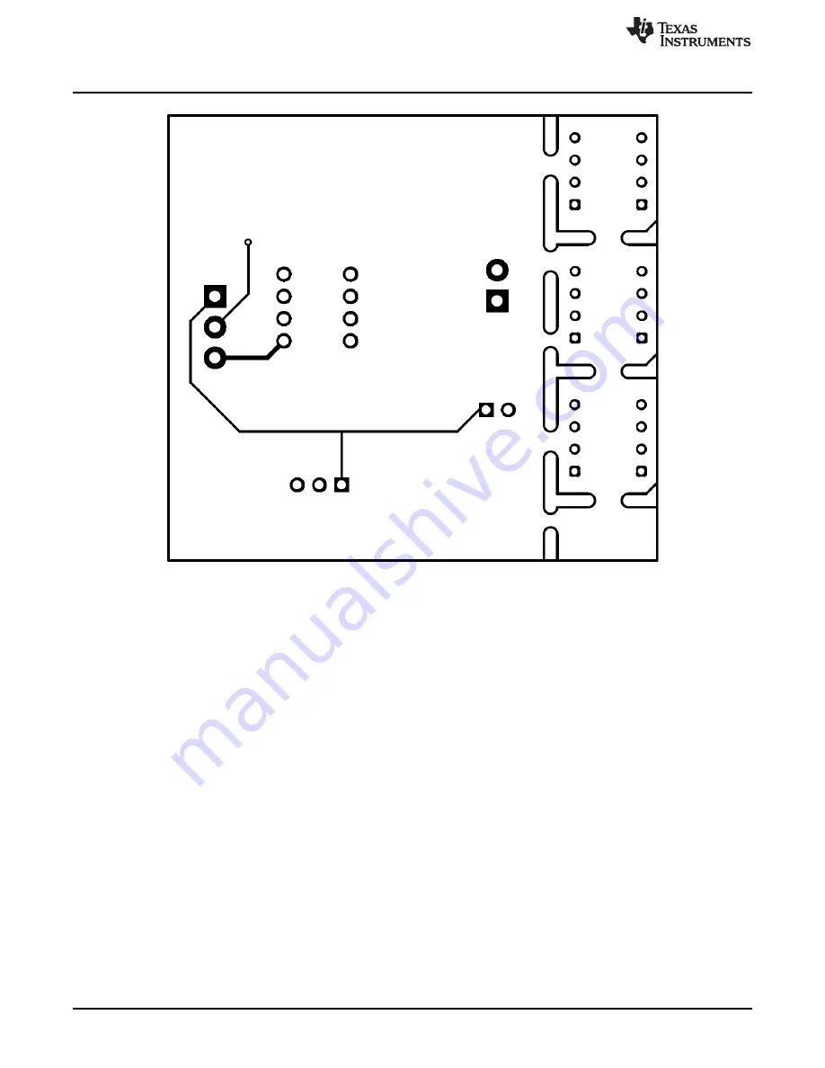
Figure 5. PCB Bottom Layer
8
INA301EVM User's Guide
SBOU154 – November 2015
Submit Documentation Feedback
Copyright © 2015, Texas Instruments Incorporated
Page 1: ...circuit board PCB layout drawings and a parts list for the EVM Contents 1 Overview 2 2 INA301EVM Hardware 3 3 Schematic PCB Layout and Bill of Materials 5 List of Figures 1 INA301EVM Test Board Block...
Page 2: ...n Center if any component is missing Make sure to check the INA301 product folder on the TI web site at www ti com for any further information regarding this product Table 1 INA301EVM Kit Contents Ite...
Page 3: ...needed Figure 1 INA301EVM Test Board Block Diagram 2 2 INA301EVM Features The INA301EVM provides basic functional evaluation of the INA301 The fixture layout is not intended to be a model for the targ...
Page 4: ...VSENSE is defined as VIN VIN and has a maximum input of V 0 20 gain in order to achieve linear output The minimum voltage output is 10 mV 2 5 Comparator Trip Point The integrated comparator in the IN...
Page 5: ...r of an alert condition D1 can be disabled by disconnecting jumper J2 Use jumper J1 to configure the comparator mode Install J1 at position 3 2 for transparent mode comparison output and at position 2...
Page 6: ...NA301EVM test board There are no components on the bottom layer Figure 4 and Figure 5 illustrate the top and bottom layers respectively of the test board Figure 3 INA301EVM Component Placement 6 INA30...
Page 7: ...www ti com Schematic PCB Layout and Bill of Materials Figure 4 PCB Top Layer 7 SBOU154 November 2015 INA301EVM User s Guide Submit Documentation Feedback Copyright 2015 Texas Instruments Incorporated...
Page 8: ...chematic PCB Layout and Bill of Materials www ti com Figure 5 PCB Bottom Layer 8 INA301EVM User s Guide SBOU154 November 2015 Submit Documentation Feedback Copyright 2015 Texas Instruments Incorporate...
Page 9: ...ock 6A 3 5mm Pitch 2 Pos TH ED555 2DS Technology 6 J5 J10 Header 100mil 4x1 Gold TH 342 10 104 00 591000 Mill Max 8 J11 J18 Socket 1x1 Height 4 27mm TH 50935 TE Connectivity 1 R1 RES 10 k 5 0 1 W 0603...
Page 10: ...ing the warranty period to the address designated by TI and that are determined by TI not to conform to such warranty If TI elects to repair or replace such EVM TI shall have a reasonable time to repa...
Page 11: ...transmitter has been approved by Industry Canada to operate with the antenna types listed in the user guide with the maximum permissible gain and required antenna impedance for each antenna type indic...
Page 12: ...ified allowable ranges some circuit components may have elevated case temperatures These components include but are not limited to linear regulators switching transistors pass transistors current sens...
Page 13: ...REMOVAL OR REINSTALLATION ANCILLARY COSTS TO THE PROCUREMENT OF SUBSTITUTE GOODS OR SERVICES RETESTING OUTSIDE COMPUTER TIME LABOR COSTS LOSS OF GOODWILL LOSS OF PROFITS LOSS OF SAVINGS LOSS OF USE L...
Page 14: ...sponsible for compliance with all legal regulatory and safety related requirements concerning its products and any use of TI components in its applications notwithstanding any applications related inf...
Page 15: ...Mouser Electronics Authorized Distributor Click to View Pricing Inventory Delivery Lifecycle Information Texas Instruments INA301EVM...