www.ti.com
Schematic and Bill of Materials
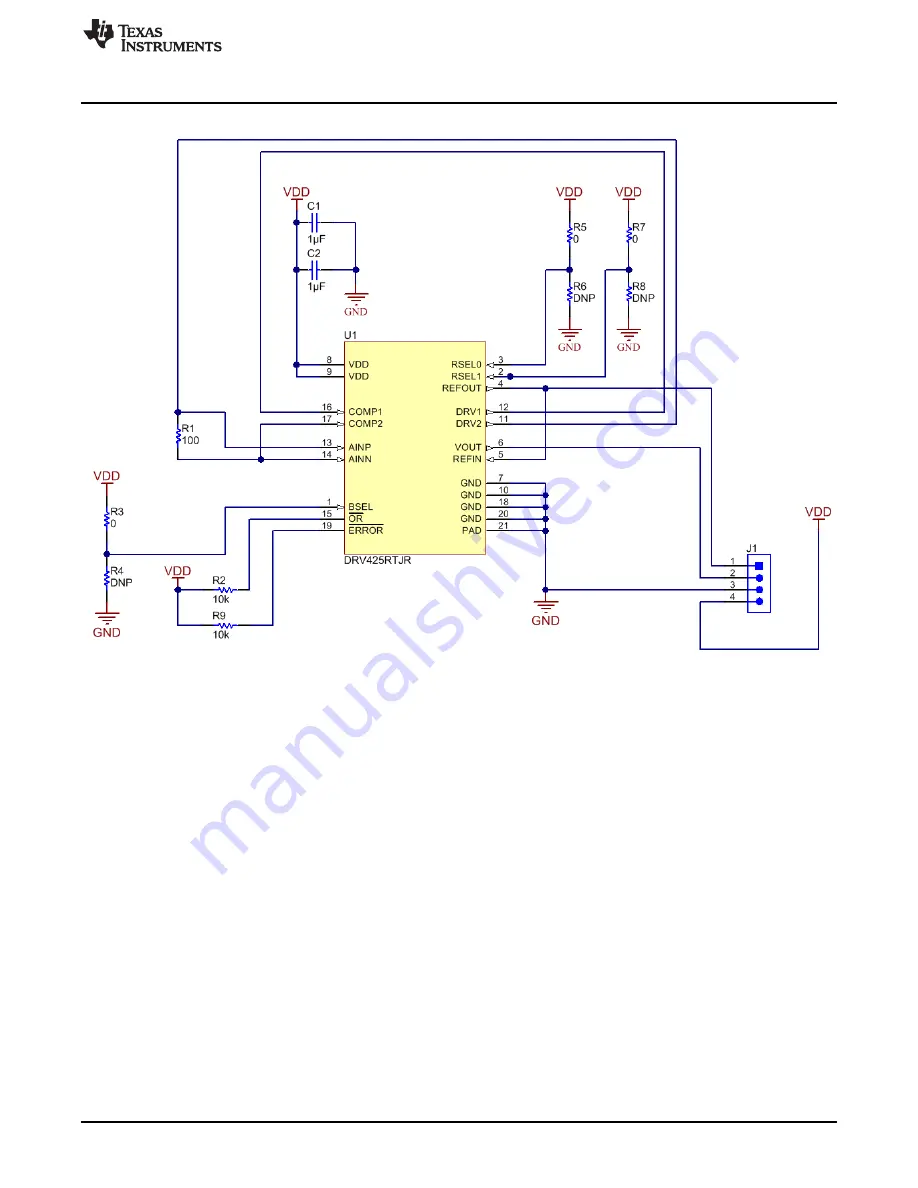
Figure 6. DRV425EVM Schematic
7
SLOU410A – September 2015 – Revised October 2015
DRV425 Evaluation Module
Submit Documentation Feedback
Copyright © 2015, Texas Instruments Incorporated
Page 1: ...agnetic Field Strength 5 4 Error vs Magnetic Field Strength 5 5 DRV425EVM Top Side Layout 6 6 DRV425EVM Schematic 7 List of Tables 1 Internal Reference Options 2 2 Factory Configuration Defaults 4 3 B...
Page 2: ...ference selection pins RSEL1 and RSEL0 as shown in Table 1 Table 1 Internal Reference Options RSEL1 RSEL0 REFERENCE VOLTAGE 0 0 Fixed Reference of 2 5 V 0 1 Fixed Reference of 1 65 V 1 0 Ratio metric...
Page 3: ...ode point of the differential amplifier output stage of the DRV425 device Reference voltages beyond VDD 2 will result in offset and gain errors 3 3 Output Voltage The output voltage of the DRV425EVM i...
Page 4: ...directly via GPIO pins on a microprocessor using fly wires 4 1 Error and Over Range R2 and R9 are 10 k pull up resistors on the Over Range OR and Error ER flag output pins respectively To observe the...
Page 5: ...500 1000 1500 2000 2500 D001 www ti com EVM Operation 4 2 1 Laboratory Measurement Results Figure 3 and Figure 4 provide measured test results for linearity and error Figure 3 Output Voltage vs Magnet...
Page 6: ...W0805100RFKEA R2 R9 RES 10 k 5 0 063 W 0402 Vishay Dale CRCW040210K0JNED R3 R5 R7 RES 0 5 0 05 W 0201 Panasonic ERJ 1GE0R00C U1 Fluxgate Magnetic Field Sensor Texas Instruments DRV425RTJR R4 R6 R8 Not...
Page 7: ...Schematic and Bill of Materials Figure 6 DRV425EVM Schematic 7 SLOU410A September 2015 Revised October 2015 DRV425 Evaluation Module Submit Documentation Feedback Copyright 2015 Texas Instruments Inc...
Page 8: ...or at R1 of 100 from the first paragraph in Section 4 4 Changed Equation 1 4 Added text To increase the sensitivity R1 can be adjusted based on Equation 1 in Section 4 2 4 NOTE Page numbers for previo...
Page 9: ...ing the warranty period to the address designated by TI and that are determined by TI not to conform to such warranty If TI elects to repair or replace such EVM TI shall have a reasonable time to repa...
Page 10: ...transmitter has been approved by Industry Canada to operate with the antenna types listed in the user guide with the maximum permissible gain and required antenna impedance for each antenna type indic...
Page 11: ...ified allowable ranges some circuit components may have elevated case temperatures These components include but are not limited to linear regulators switching transistors pass transistors current sens...
Page 12: ...REMOVAL OR REINSTALLATION ANCILLARY COSTS TO THE PROCUREMENT OF SUBSTITUTE GOODS OR SERVICES RETESTING OUTSIDE COMPUTER TIME LABOR COSTS LOSS OF GOODWILL LOSS OF PROFITS LOSS OF SAVINGS LOSS OF USE L...
Page 13: ...sponsible for compliance with all legal regulatory and safety related requirements concerning its products and any use of TI components in its applications notwithstanding any applications related inf...
Page 14: ...Mouser Electronics Authorized Distributor Click to View Pricing Inventory Delivery Lifecycle Information Texas Instruments DRV425EVM...