Quick Start Guide
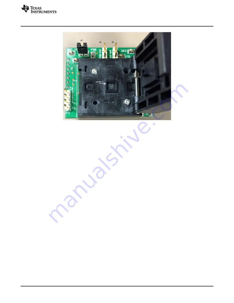
Figure 3. DRV10963 Orientation Inside Daughterboard Socket
5.3
Jumpers and Switch Setup Settings
On the daughterboard:
1. Make sure that only jumper J1 is populated, jumper J2 and J3 all 3-pins shall be open
On motherboard:
1. Make sure that all jumpers J1, J2, and J3 are populated
2. Switch S1 should be in the off position and switch S2 in the I2C-GUI position. DRV10963 PWM input
pin has dual functionality, that is, it serves as speed control input as well as clock signal for I
2
C. Switch
S2 provides a means to configure the PWM input pin for speed control or I
2
C clock.
5.4
Powering-Up EVM
DRV10963 EVM requires two power supply sources, that is, 5 V and 6.2 V to work with the GUI to enable
I
2
C interface for register configuration. Note that programmed device needs only one 5-V supply in the
final end-application circuit. Use the following sequence to power-up the EVM and to establish a
successful connection with the GUI:
1. Do not power up the power supply. First, connect the power supply ground to pin GND, the 6.2 V to
pin V_Testmode, and 5 V to PowerIn on the motherboard at connector P3. At this point, make sure
that switch S1 is in the turn-off position and the “USB2Any” board is not connected to the motherboard.
If using a lab power supply, it is recommended to set the current limit of both power supplies to 1.5 A.
2. Turn the POT-R17 fully CCW (counter-clock wise). This keeps the speed PWM input to the minimum
value.
3. Connect the 3-phase terminal of motor to connector P4 on the daughterboard. It is not important to
observe the polarity as it only determines the direction of rotation.
4. Now power up the board and turn switch S1 to the “on” position. Check LED1, LED2, and LED3. All
should turn green.
5. Connect USB2Any box first, via the supplied USB cable to the computer. Then connect the 10-pin
ribbon cable to the USB2ANY connector on the motherboard.
7
SLAU643 – July 2015
DRV10963 Evaluation Module
Copyright © 2015, Texas Instruments Incorporated


