Quick Start Guide
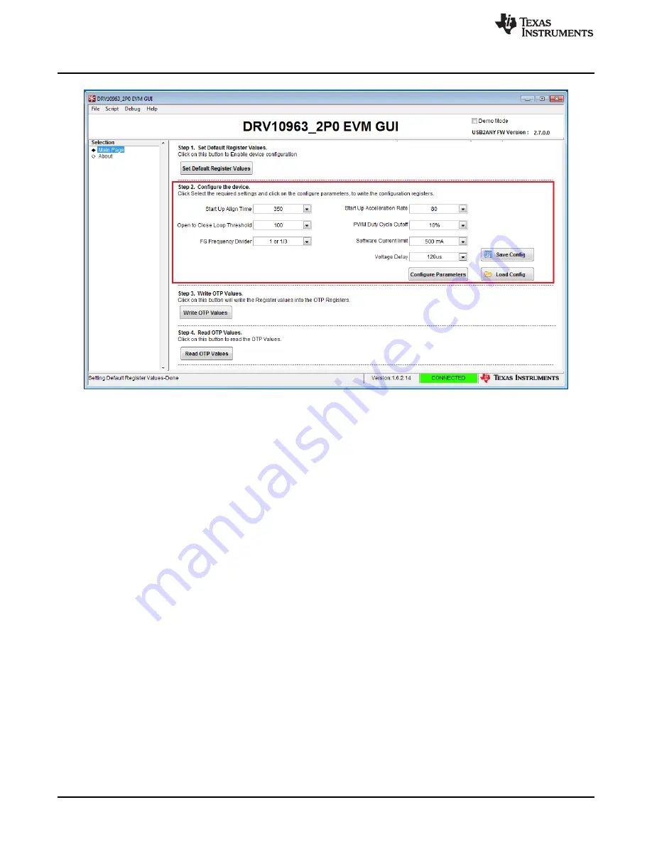
Figure 6. Default Configuration Parameters
4. To facilitate the tuning at different speeds or across a speed range, the EVM provides a TLC555 timer-
based PWM generation circuit and potentiometer (R17) to adjust the duty cycle of PWM to control the
speed of the motor. To enable speed control via POT-R17, change the switch S2 position to PWM
Speed Control mode. Turn the POT-R17 clock-wise to increase the motor speed and counter-
clockwise to reduce it.
5. In case motor performance is not satisfactory with default values or further optimization is desired, try
three other factory-programmed device options before attempting to customize parameters. This would
benefit in production phase because all versions of factory programmed devices can be easily
procured and used directly without the burden to programming the OTP values. The GUI comes with
three .txt files corresponding to the three remaining factory-programmed devices.
6. To test motor performance with the DRV10963JM version, short the jumper J1 back. This will stop the
motor. Referring to
, left-click the “Load Config“ button, browse to the GUI installation directory
for 3 .txt files in your PC and select DRV10963JM.txt.This will load the register with configuration
parameters corresponding to DRV10963JM. Refer to
to check configuration parameters
corresponding to the DRV10963JM version. In same way, load and configure other versions of
DRV10963 to test the performance. To enable motor spin, open the jumper J1 on the motherboard and
use POT R-17 for speed control.
10
DRV10963 Evaluation Module
SLAU643 – July 2015
Copyright © 2015, Texas Instruments Incorporated


