Note
• The board can also be powered over USB by populating J9 and connecting the USB cable to a 5V
source such as a laptop. Ensure the external supply is not connected to turrets or barrel jack when
using the USB power. This header has a 5-V maximum limit.
2.2.2 SMI Connection and Communication
2.2.2.1 Onboard MSP Connection
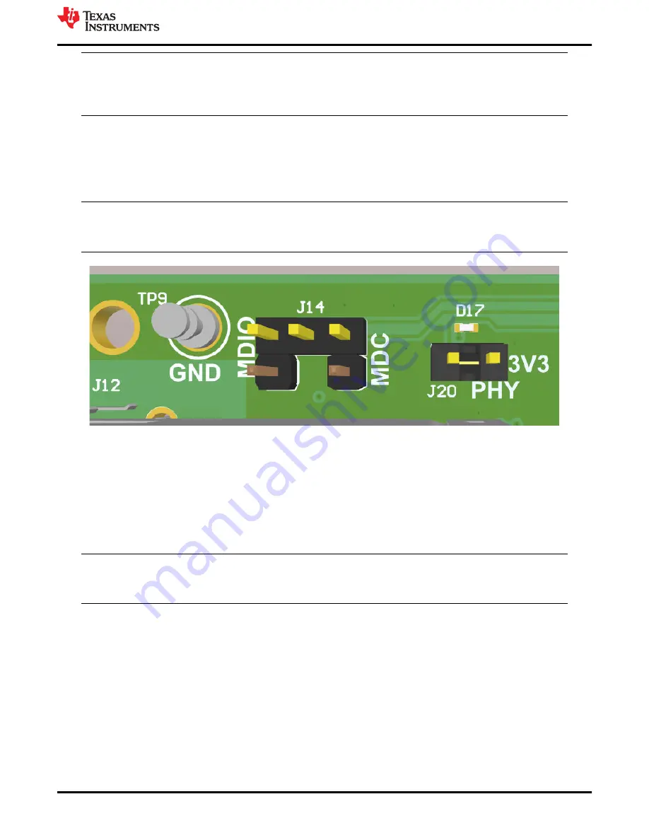
• There is no additional action needed for using the onboard MSP430 device for MDC/MDIO configuration.
Connections are done at bottom of the board and hence no jumpers should be placed on J14.
Note
• To use external MSP connection, please connect MDC of MSP to top-right most pin of J14 and
MDIO to top-left most pin of J14.
Figure 2-5. Onboard MSP Connections for MDIO and MDC
2.2.2.2 Downloading USB2MDIO for SMI
The onboard MSP430 comes pre-programmed and ready to use. When using this EVM for the first time on a
Windows 10 PC, MSP430 drivers and USB-2-MDIO software utility need to be installed. USB-2-MDIO software
can be used for accessing the PHY's registers. The software is available to download along with its user's guide
in the link.
2.2.2.3 SMI Interface
Note
• DP83TC813 PHY_ID on EVM is 10
• DP83867 PHY_ID on EVM is 01
After installing and enabling the USB2MDIO tool, power on the EVM and connect to the computer through the
micro-USB port. Verify communication on each PHY by reading register 0x0001.
• DP83TC813 will read 0x1 = 0x0061 with no link partner and 0x1 = 0x0065 with a link partner connected
• DP83867 will read 0x1 = 0x7949 with no link partner and 0x1 = 0x796D with a link partner connected
• To enable analog loopback on the DP83TC813, write 0x0108 to address 0x0016
2.2.3 Master and Slave Mode Selection – DP83TC813
• Master Mode
– Place shunt across J2
• Slave Mode
– Leave J2 open
Introduction
SNVU825 – MAY 2022
DP83TC813EVM-MC User's Guide
5
Copyright © 2022 Texas Instruments Incorporated


