


VREF = DAC_VALUE
·
2.5
V
¾
4095
The Windows Application
3.3
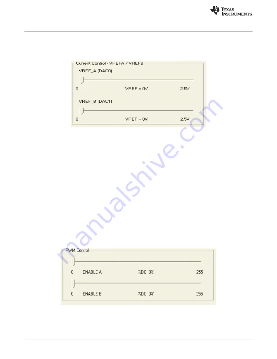
Updating DAC Output for Current Control (VREFA and VREFB)
If the DRV88xx has been configured to accept VREF analog voltages through the microcontroller DAC
outputs (refer to Jumpers section), then the slider bar on the Current Control frame can be used to set the
VREF voltage.
Figure 8. Current Control
The 12-bit DAC channels 0/1 are connected to the DRV88xx VREF analog inputs ABVREF and CDVREF.
Changing the DAC digital value from 0 to 4095, changes the analog voltage at the respective VREF pin
from 0 V to 2.5 V respectively, following the equation:
(1)
Where:
VREF is the output voltage.
DAC_VALUE is a number from 0 to 4095.
Moving the sliders will update the “VREF = xV” caption below each respective slider with the result of the
previous equation giving the user an idea of what analog voltage is being presented at the reference
voltage input.
3.4
DC Motor Speed Control (PWM)
The DRV8802-14 can be utilized to control DC motors. For the purpose to control DC motor speed, a
slider is provided which applies a PWM to the ENABLE line. The PWM slider consists of an 8-bit number
so position from 0 to 255 are obtained. The MSP430 directly transforms this 8 bit number into the
respective duty cycle. PWM frequency is around 31.25 kHz.
Figure 9. Duty Cycle Indicator
8
CPG004_DRV88xx Evaluation Modules
SLVU361B – April 2010 – Revised October 2013
Copyright © 2010–2013, Texas Instruments Incorporated