


December 2011
Web sites:
www.ti.com/lprf
E2E Forum:
www.ti.com/lprf-forum
Make sure to subscribe to the Low-Power RF
Newsletter to receive information about updates to
documentation, new product releases, and more.
Sign up on the TI web pages.
CC2543-CC2544 Development Kit Quick Start Guide
Opening the Box and Running the
Packet Error Rate
Test Application
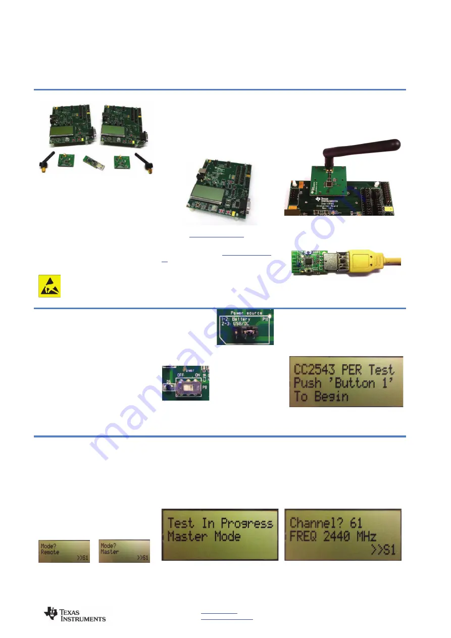
1. Kit Contents
•
2 x SmartRF05EB (the two large boards)
•
2 x CC2543 Evaluation Module (CC2543EM)
•
2 x Pulse W1010 Antennas
•
1 x CC2544 Dongle
•
Cables
•
Documentation
The RF boards in this kit are FCC and IC
certified and tested/complies with ETSI/R&TTE
over temperature from 0 to +35°C. The antenna,
W1010 from Pulse, is a ¼ wave dipole antenna
with 2 dBi gain.
Caution!
The kit contains ESD
sensitive components. Handle with
care to prevent permanent damage.
2. Hardware Requirements
To run the example described in this Quick
Start Guide, you would need either two
CC2543Ems
mounted
on
SmartRF05
Evaluation Boards (SmartRF05EB - Rev 1.8.1
or later). Or a single CC2543EM mounted on
a SmartRF05EB and a CC2544 Dongle
(powered through USB). The SmartRF05EBs
are included in the CC2543-CC2544DK.
More information about the SmartRF05EB can
be found in
www.ti.com/lit/swru210
.
The CC2543EM boards can also be plugged
into a battery board (see
www.ti.com/tool/soc-
bb
) for standalone operation.
3. Hardware Setup
Connect the antenna to the SMA connector on
the CC2543EM. Tighten the antenna’s screw
firmly on to the SMA connector. If not properly
connected,
you
might
see
reduced
RF
performance.
Next, mount the CC2543EMs firmly on to
connectors P5 and P6 on the SmartRF05EB.
The CC2544 Dongle can be connected to any
USB port to power the device.
Caution!
To minimize risk of injury, avoid
touching
components
during
operation
if
symbolized as hot.
4. Power Options
There are several ways of applying power to the
SmartRF05EB.
•
2 x 1.5 V AA Alkaline Batteries
•
USB
•
External Power Supply
For the batteries and USB, there are voltage
regulators on the SmartRF05EB that will set the
on-board voltage to 3.3 V. The external power
supply should set a voltage that does not exceed
3.3 V.
Note that there should only be one
active power source at any one time.
Warning!
To minimize risk of personal injury or
property damage, never use rechargeable
batteries to power the board.
5. Power the
Boards
Find jumper P11 on
the top side of each
SmartRF05EB. This jumper is used to set the
power source for the board. Set P11 to “1-2” if
you are using battery power. Set P11 to “2-3” if
you are using USB or an
external power supply.
Once you have set P11,
find switch P8 on the top
side
of
each
SmartRF05EB. To power up the boards, flip the
switch from the “OFF” position to “ON”.
Do
not
leave
EVM
powered
when
unattended.
6. Start-up Screen
The CC2543EMs and the CC2544 Dongle
will be pre-loaded with a Packet Error Rate
(PER) test application. The LCD screens on
the two SmartRF05EBs should display the
messages below:
A green led (LED2 on CC2544Dongle, LED1
on SmartRF05EB) will blink continuously
After the application has started.
7. Choosing Mode
The application can be used between two
CC2543EM’s or between a single CC2543EM
and the CC2544 Dongle. There are two possible
modes of operation called “Remote” and
“Master”. The CC2544Dongle is set to master by
default as it is the only option for this device in
this application. After button S1 is pushed at the
start up screen, the mode selection screen
(showed to the left below) will appear. The
Remote mode is shown by default. Press the
joystick up and down to change between master
and remote mode and press button S1 to
confirm.
In the remote mode all the parameters for the
current PER test must be set up before the test
begins.
8. Master Mode
In “Master” mode, the radio will repeatedly (once
every 10 milliseconds) send out a “beacon”
signal (250 kbps, GFSK modulation, 160 kHz
deviation, 2479 MHz) and listen for a response
from the remote device. Once the beacon is
acknowledged by the “Remote”, the actual PER
test begins. During the PER test, packets are
sent at a fixed repetition rate of 10 msec.
No more actions are needed from the user for
this master device to work.
9. Frequency Selection
When the remote mode is chosen, a series of
settings must be configured to set up the link for
the PER test. The frequency must be selected
first. Move the joystick up or down to change the
frequency (channel) and press S1 to confirm the
choice.


